Intro#
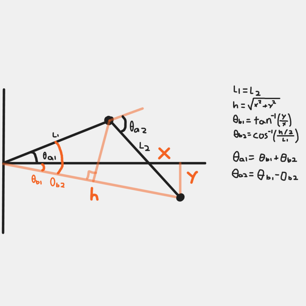
At the start of 2024 I was working on an online robotics course in my free time, and wanted to create a simple robot to apply some of the theory I was learning. After some research I decided a basic SCARA (Selective Compliance Articulated Robot Arm) style would be an easy place to start, with only 2 degrees of freedom plus a simple end effector.
I did this project some time before putting this website together and only completed a rough (somewhat) working prototype, but the build and results will be documented here.
Build#
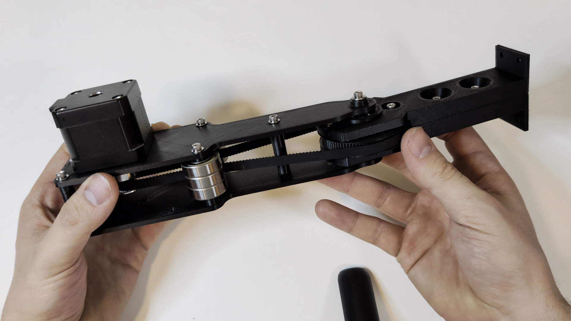
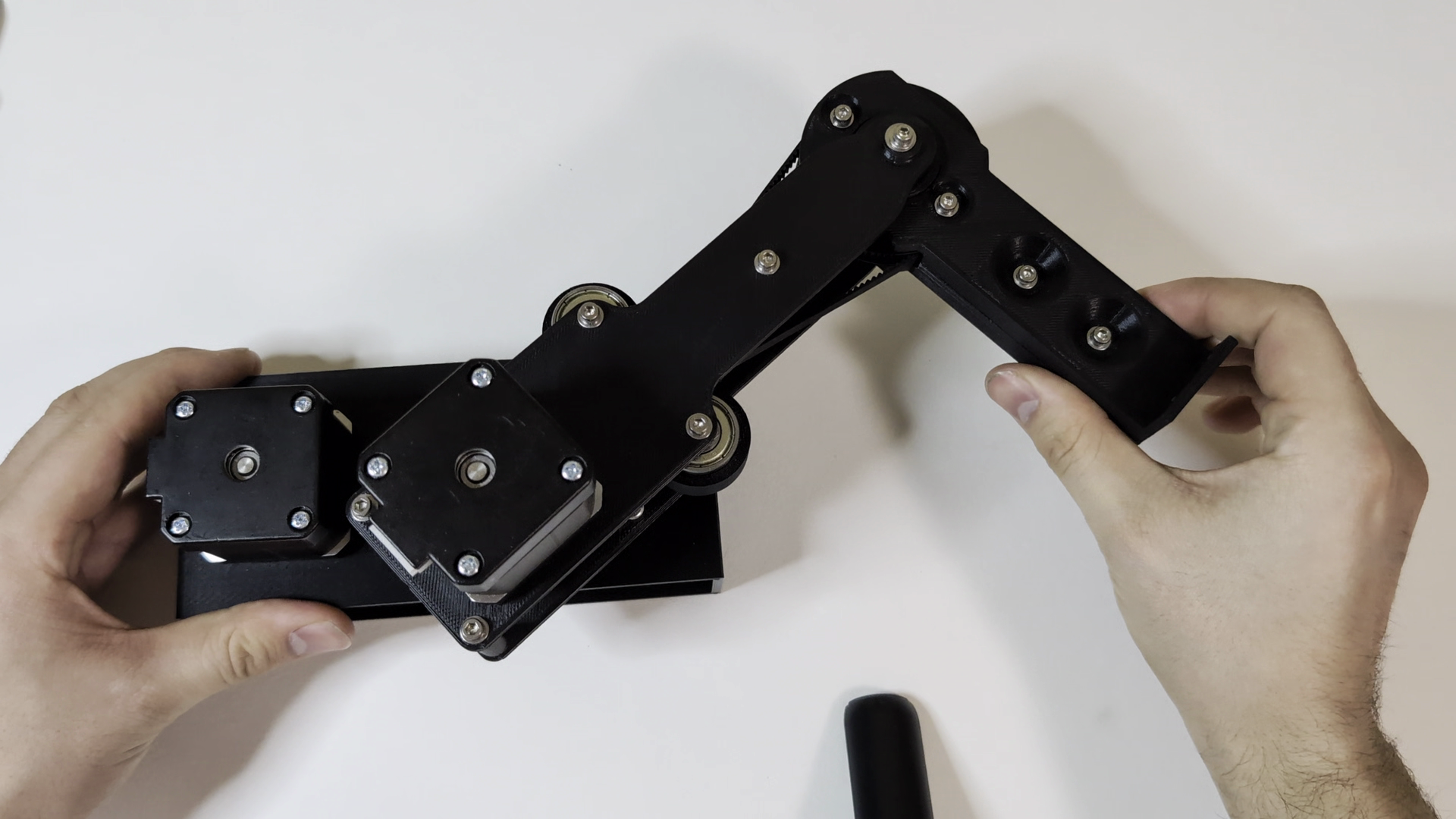
I had a couple NEMA 17 stepper motors, a pulley and belt kit with belts of various sizes, some bearings, and an Arduino on hand. After ordering some small stepper drivers, I decided to design a simple prototype using just these components. Using FreeCAD I modeled up an arm with equal link arm segment lengths and 4:1 gear ratios from the motors to each joint using the belts I had.
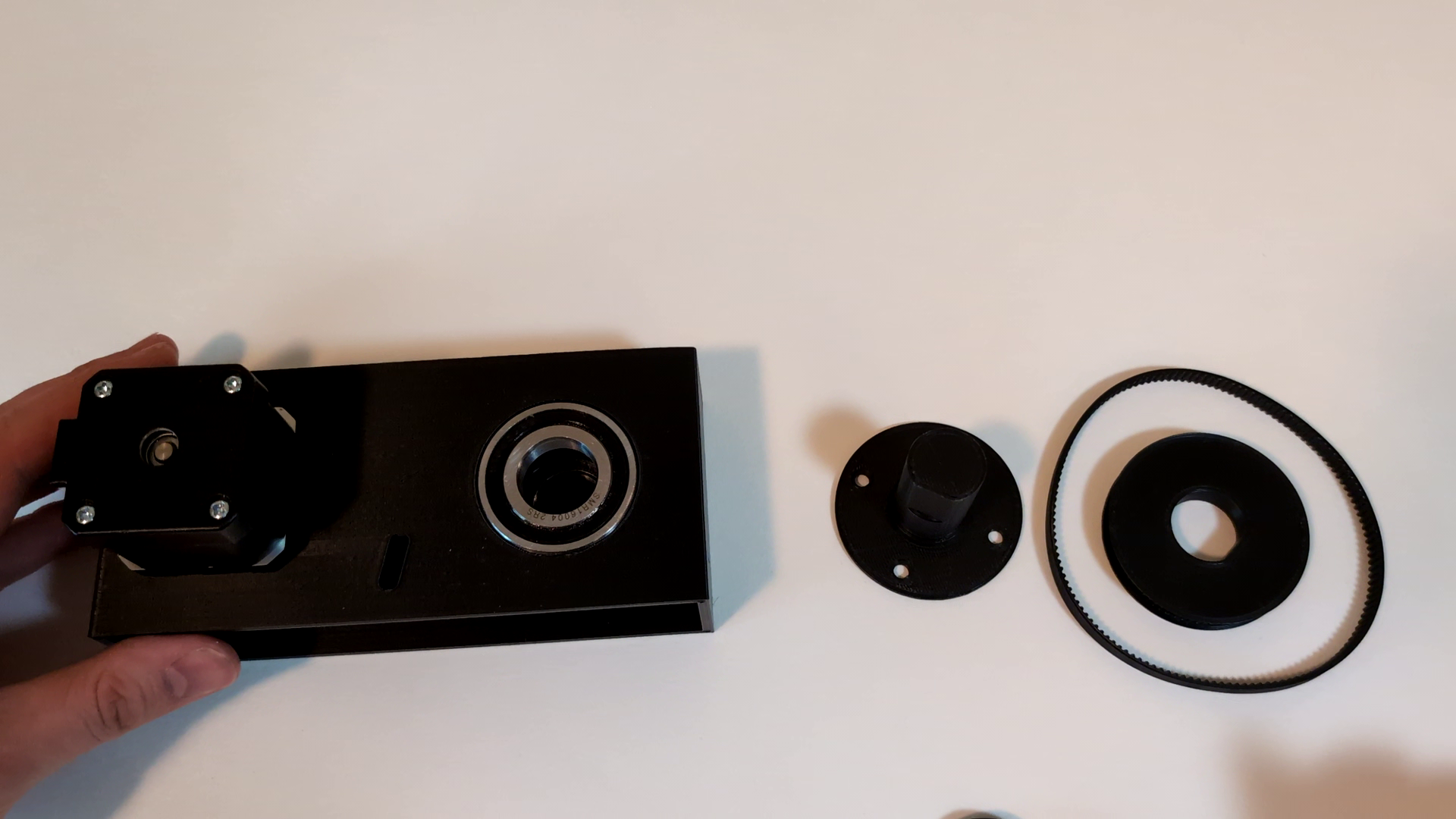
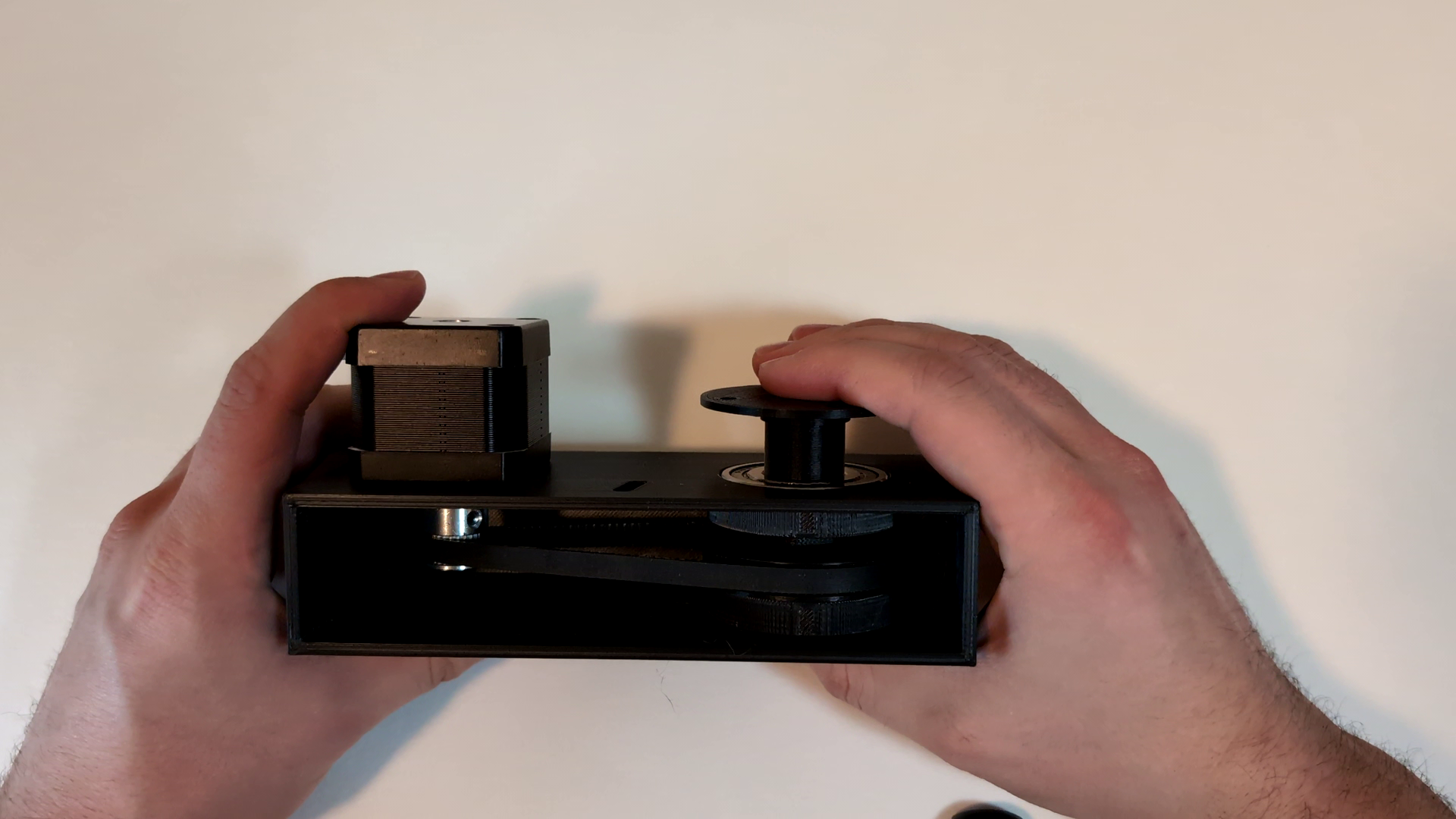
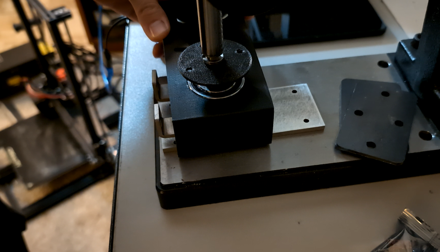
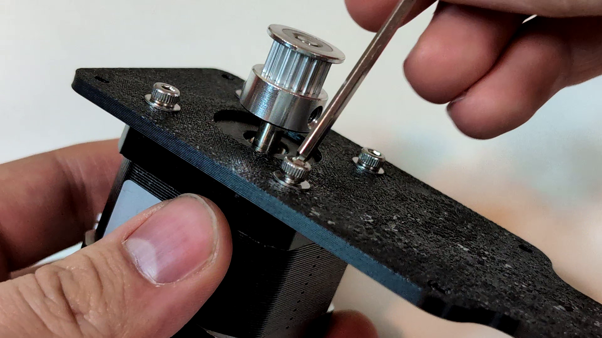
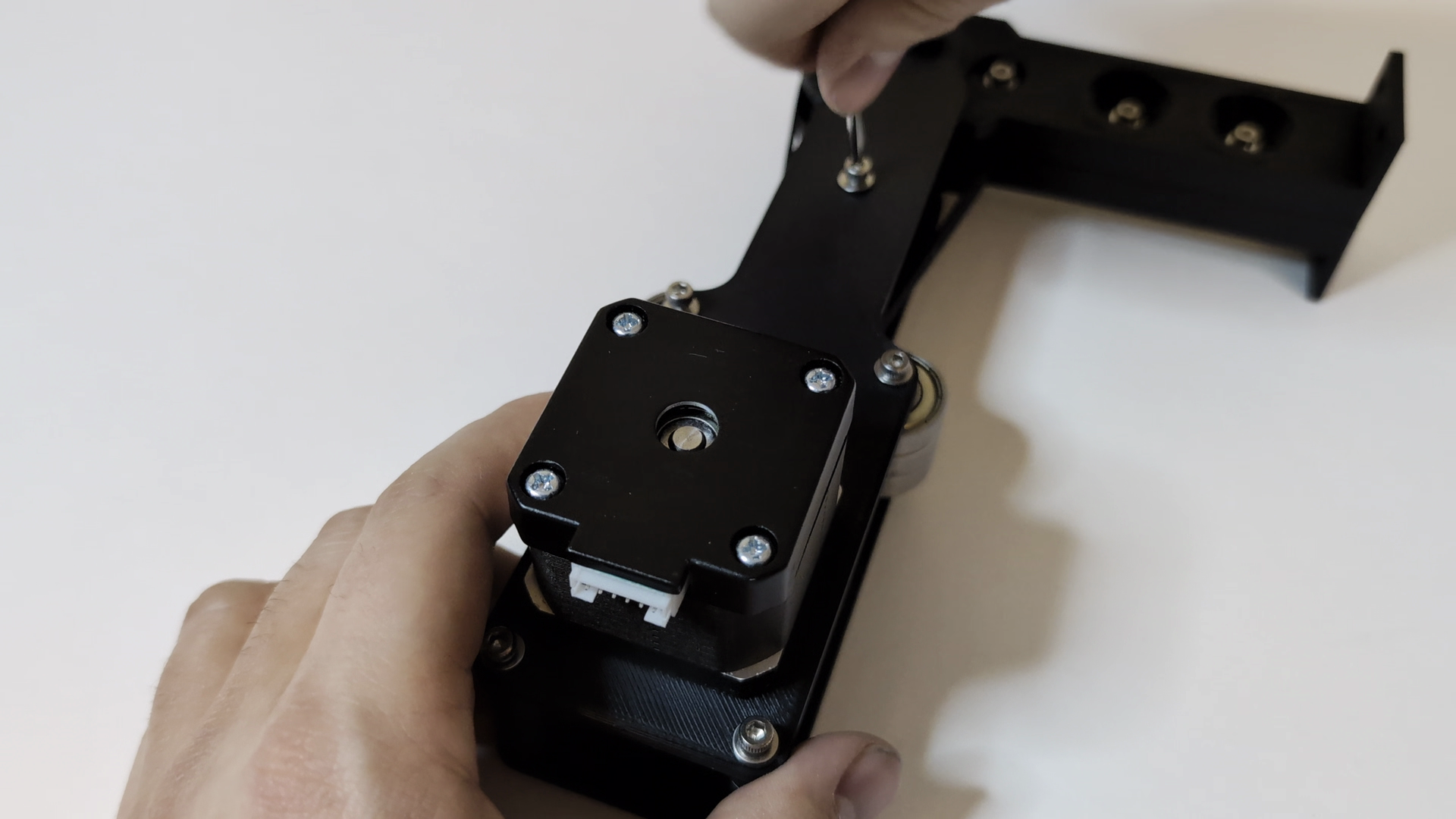
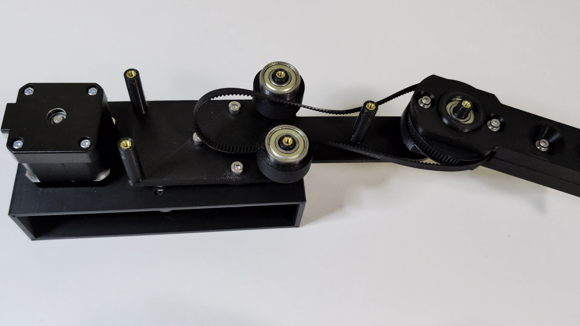
The first joint connecting the base and link was fully press fit, with bearings pressed into the base and a keyed pulley and shaft pressed through the bearings. The motor is simply attached with screws and an adjustable tensioner using bearings as an idler is then installed.
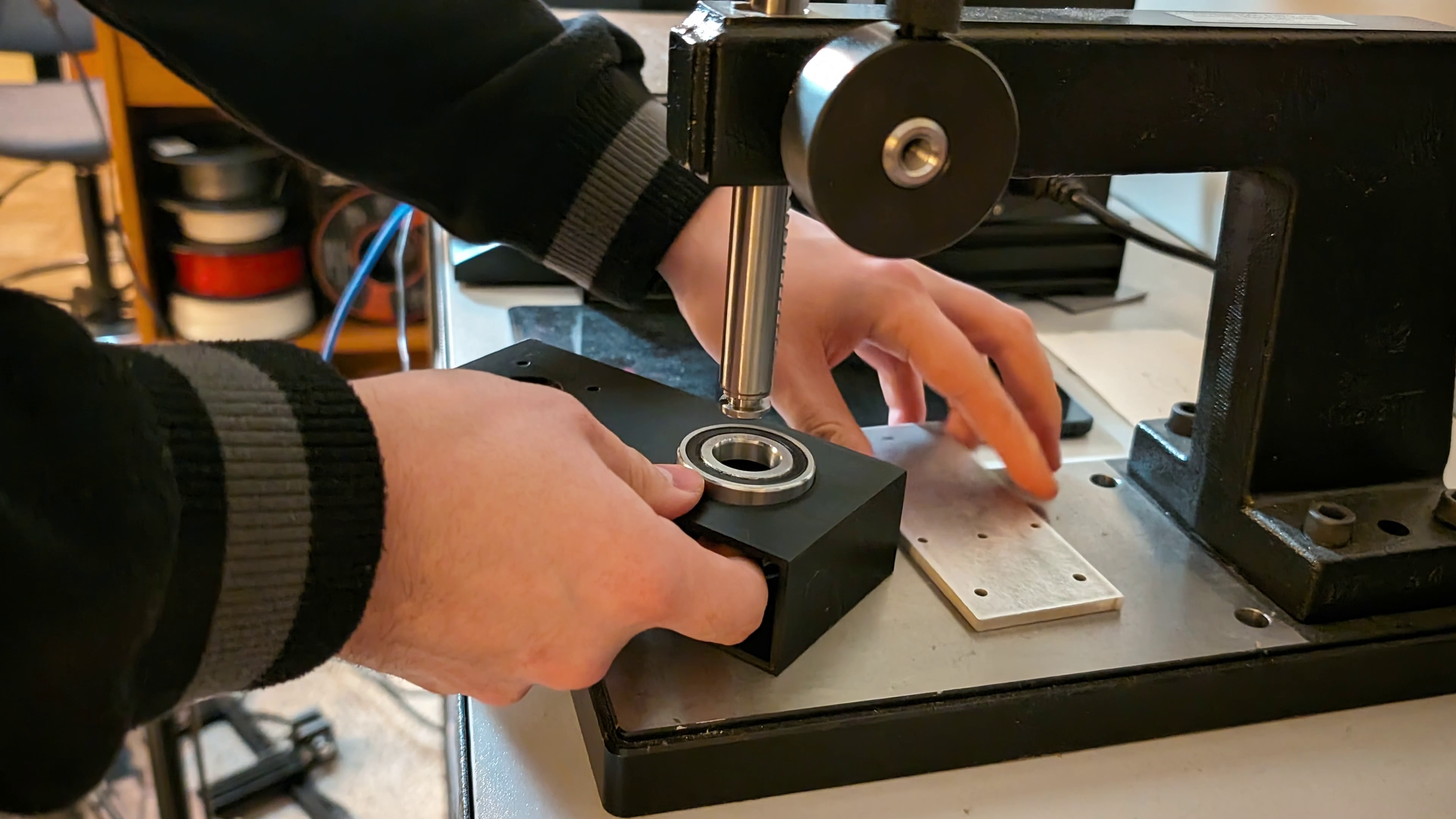
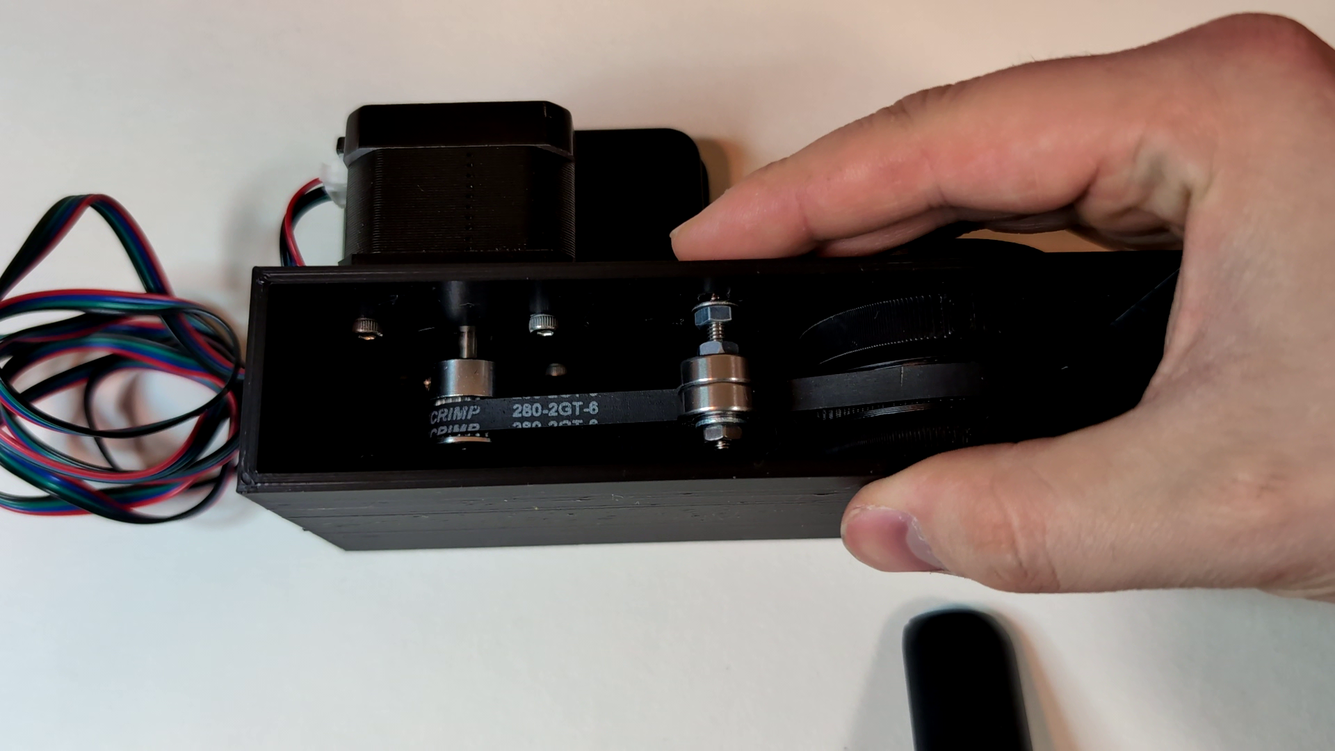
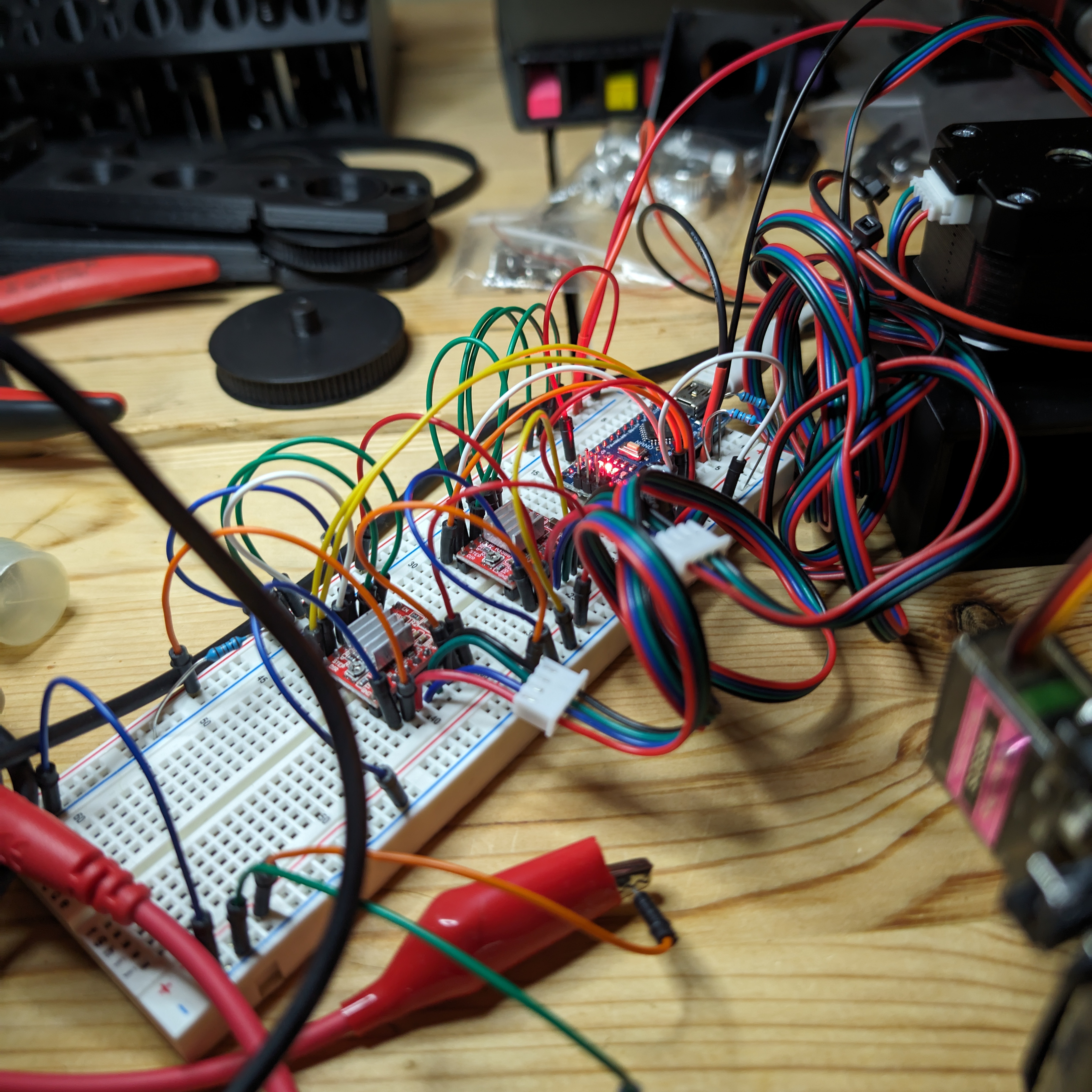
The first test using simple code with Arduino, A4988 stepper drivers, and the base plus a test part connected to the joint confirmed the electronics and joint mechanics worked.
Assembling the second and third link (arm segments) went well except for the belt skipping due to low tension.
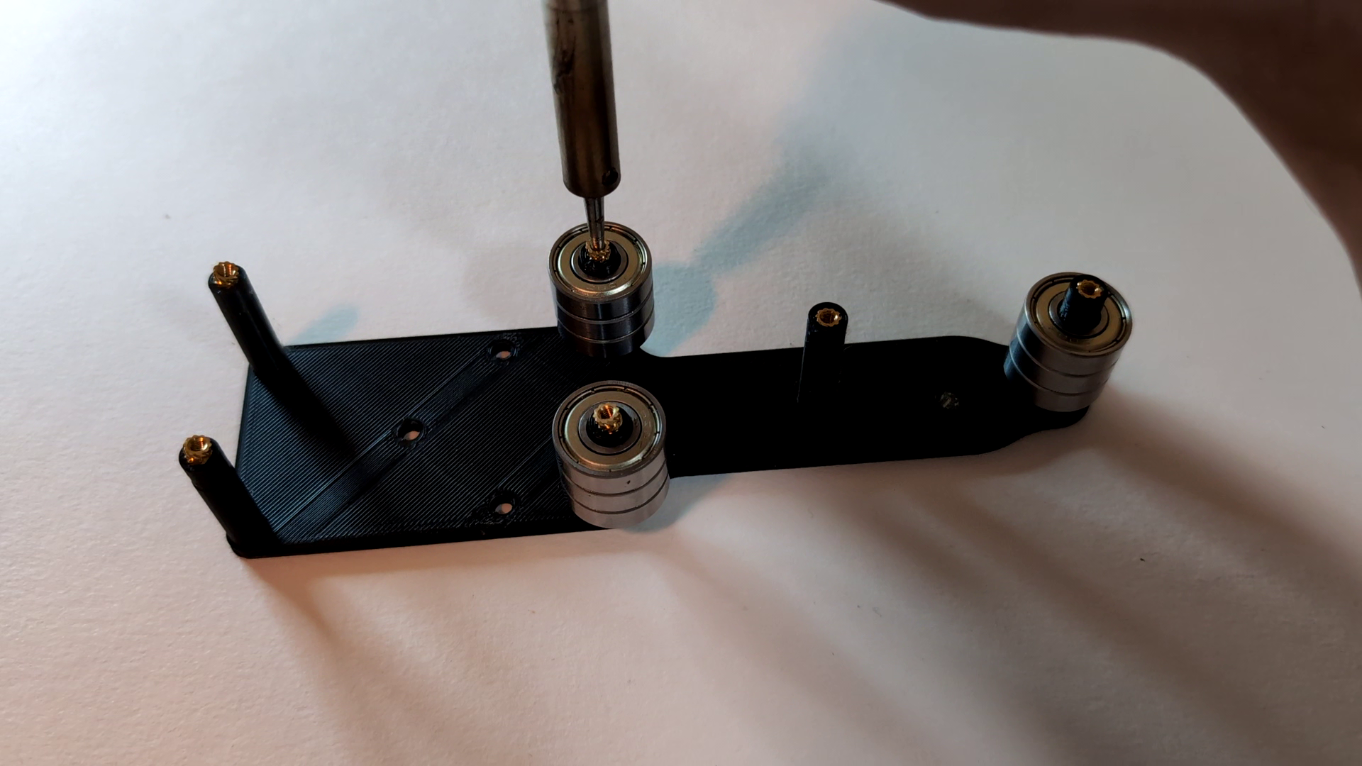
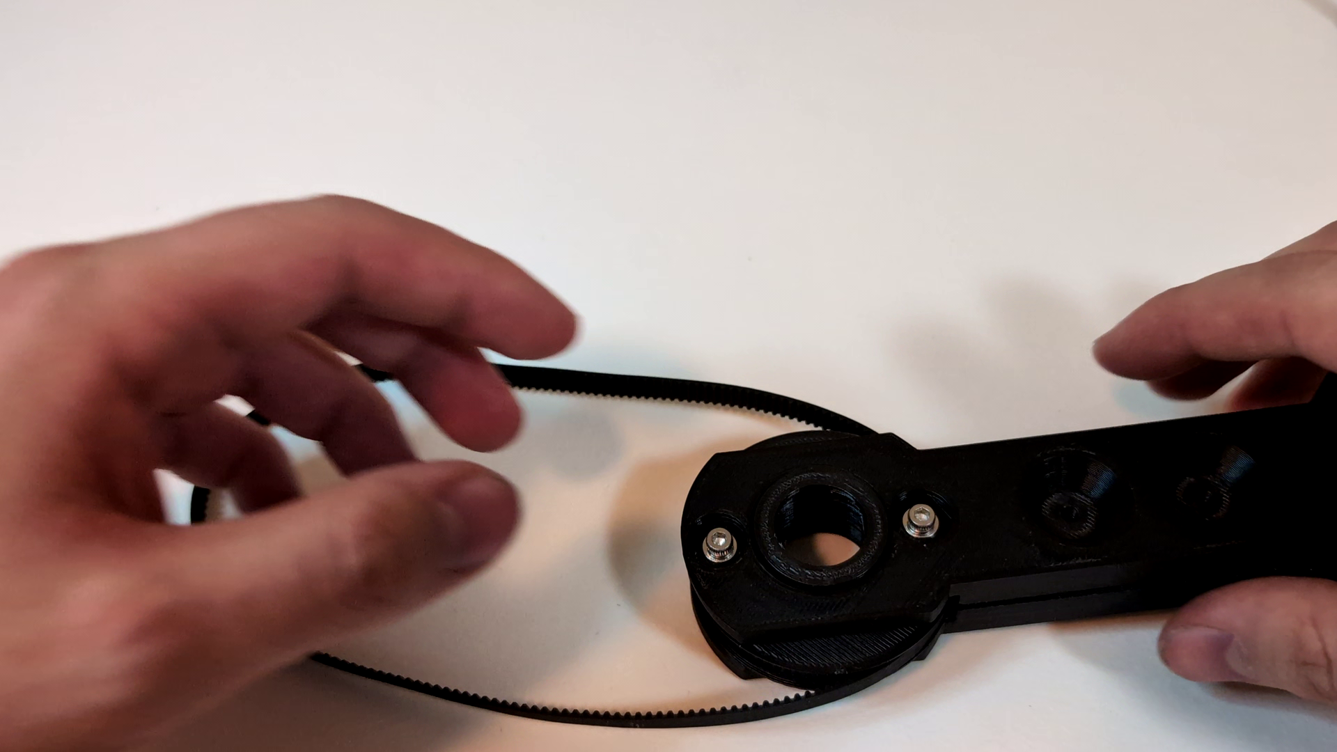
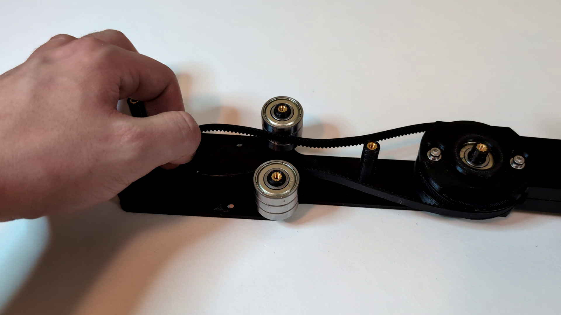
This was fixed with a sleeve over the tensioner bearings.
After retrofitting some microswitch end stops for homing, and some Arduino coding, it homed successfully.
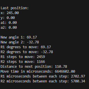
After writing some code and fitting a servo controlled pen as the end effector, I tried some simple drawing movements starting with a square. My code definitely had some issues to start, with pulse timing being a problem. I also simply had the joints move from one angle to another calculated angle based on the location given, which resulted in these arcs. Interpolation would be required to make the lines straight.
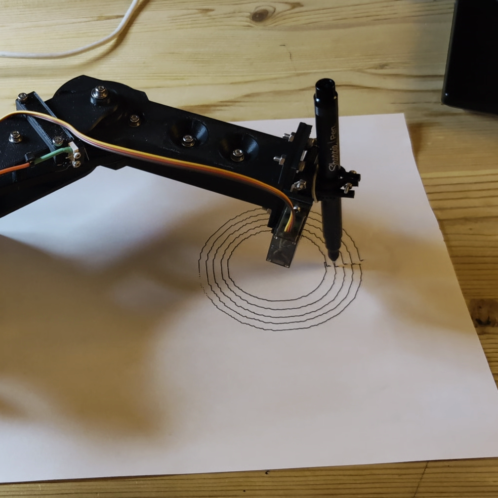
I then wrote a simple script to draw concentric circles, generating 180 points around each. This resulted in a relatively more accurate drawing, but still nothing pretty.
for (int i = 0; i < 8; i++) {
        for (int j = 0; j < 180; j++) {
            x =  ((40 - i*4) * cos((double)j * 2 / (180 / PI))) + 193;
            y = ((40 - i*4) * sin((double)j * 2 / (180 / PI)));
            moveToPos(&lastPosition, x, y, 120);
            if (j == 0) {
                penServo.write(penDownDeg);
                delay(200);
            }
            if (j == 179) {
                penServo.write(penUpDeg);
                delay(200);
            }
        }
}Conclusion#
My plan from this point was to program the controller to accept streaming G-code and to write a G-code sender program which could convert an SVG to G-code, and then interpolate points for smooth lines. I got as far as accepting a G-code command through serial and moving to a location, as well as converting a test SVG file to G-code using Vpype, but never got the controller and sender fully working before becoming busy with other things in life.
Some things that I’m looking forward to improving on the next similar project are:
- Rigid joints using better bearings and properly joined links (flange/retaining ring)
- Efficient gearing - to experiment with harmonic/cycloidial drives
- Better controller code using a more powerful microcontroller
- Different and more useful end effectors
For now I’m calling this version of the arm complete as a first experiment, and taking the lessons learned for another robot arm build in the future.
This was a rough prototype, but if you want to take a look at the CAD or code, it’s available to download here.