Intro#
If you’re a musician and haven’t played with a looper pedal, I’d highly recommend it. More likely, if you’re reading this article, you already know how fun playing with a looper is and how much creativity it can enable with your instrument. Many people even gig solo with a looper pedal allowing them to perform as a one-man band. To do this, however, a simple one-track looper like the BOSS RC-1 that I’ve personally been using up until this point is very limiting. With fully featured multi-track loop stations like the BOSS RC-600 and Sheeran Looper X costing upwards of $1000, I decided to start developing a versatile open-source multi-track loop station that can be built with common hobbyist parts and equipment.
I’m intending it to be viable as an all-in-one type pedal that lets you plug in a guitar (or other electric instrument), MIDI controller, microphone, and hop right into creating “full band” sounding live loop performances with no extra equipment required.
Intended Features#
Starting perhaps somewhat ambitious, in this first version I’m aiming to include the following features:
- At least 4 Loop tracks with start and stop switches (double tap sucks)
- Built-in MIDI player to allow for drum or synth loops to be created right in the pedal
- Built-in drum loops (and a way to upload your own)
- Instrument, microphone, and MIDI (USB) inputs
- Touch screen display with UI
- Stereo outputs and headphone jack out
- Tap tempo and measure sync (start and stop loops on beat 1)
- Basic built-in effects that can be turned on per track or assigned to a switch
Hardware Design#
Electronics#
Main Modules#
This project calls for a processor with a powerful enough CPU to record, mix, and play multiple audio tracks in real time, while also running a display with a UI. Importantly, it also requires enough RAM to store multiple tracks in memory and an ADC + DAC to convert audio from analog to digital and back.
For these core functions, I decided to use a Raspberry Pi 4B paired with a HiFiBerry DAC+ ADC sound card. These are easy to prototype with thanks to the GPIO header pins, but also make transitioning to a more professional setup later relatively smooth using the Compute Module 4 and the ADC/DAC (PCM1863/PCM5122) chips directly. One problem is that Linux is not a real-time system by default and latency or xruns (clicks or pops) would be unacceptable for this application, but with some OS modifications it should be able to get down to a smooth <10ms latency.
For the UI, I want to use a touchscreen display just as a personal preference since there will be many menu options, and navigating menus with rotary encoders is annoying in my opinion. I may implement support for knob navigation in the future, but if you’re following along and would prefer to save money with a non-touch screen and encoders feel free to fork the project and modify it yourself.
The screen needs to fulfill a few requirements:
- DSI connector (ribbon cable). SPI would possibly interfere with the audio card, and HDMI would add unnecessary bulk and cables within the assembly (on top of likely being harder to implement in a future PCB).
- IPS display. An IPS display that provides a good viewing angle is a necessity for a display down in front of you on the ground.
- Capacitive touchscreen. Almost goes without saying, but the resistive touchscreens you need to press down with a stylus won’t work for this.
- Controllable backlight and decent brightness.
Within these criteria I selected a ~$50 5" monitor off of Amazon.
Stereo Consideration#
One question that matters for downstream decisions is: how important are stereo inputs and outputs? It adds potentially unnecessary complexity, especially if the most common use case is plugging into a single amplifier or getting mixed to mono anyway when performing. However, actually getting stereo effects and being able to mix the loop tracks on the pedal would be pretty sick if using a stereo audio system. Dual outputs would also allow for drums/synth to go to one output and guitar to the other, as well as other options that can be added in software later.
For this prototype build, I’m looking at using a sound card with only two input channels, and I think using these as a mono instrument input and a microphone input is likely more useful than stereo instrument inputs. I will include stereo outputs though to allow for track mixing/stereo effects. With a custom board design later, more inputs can be added as the codec does support multiple channels despite the sound card not implementing them.
Supporting Circuits#
Buffer Circuit
If an instrument is plugged directly into the sound card, it needs to come from a low impedance source or the sound quality could be affected.
An electric guitar has high impedance so we need a circuit with high input impedance to match the guitar and low output impedance to match the sound card, ideally while not modifying the signal at all.
Microphone Preamp
The pedal will have an XLR input for a dynamic microphone, but before the signal can go to the sound card it needs to be amplified. For this a small amplifier circuit is required.
Auxiliary Components#
Instrument Jacks
Since we will be implementing stereo outputs and eventually stereo inputs, we need to be able to detect if a cable is connected to the “R” jack to determine if the output is mixed to mono or not. This means we’ll need switched input jacks.
Internal Wiring
To avoid picking up noise from the raspberry pi I’m planning on using shielded cable, and using copper foil on the inner cavity to prevent interference.
Switches
Of course, 10 footswitches will also be needed. Eight for the loop tracks and two programmable ones (stop all, effect toggle, etc.) These will be momentary, with any toggling happening in software and so that a double tap or hold can be detected.
Indicator LEDs To indicate the status of each track individually the touchscreen UI could be used, but actually seeing an indicator of the current state near each switch would be more clear and less cluttered than using the touchscreen. For this I already have some a roll of WS2812B adressable LEDs which can be daisy chained and controlled individually through software just using one gpio pin.
Power
Ideally the Raspberry Pi 15W USB-C charger would be enough to power everything, with the the maximum current draw of the different components being:
- The Pi itself: ~1.5A
- Preamp and buffer: <10mA
- Indicator LEDs: ~360mA
- Touchscreen: ~500mA
- HiFiBerry module: <60mA
This comes to at most ~2.5A, which means a standard 5V 3A USB-C charger will be adequate. Given this, the plan is to use the 5V rail on the Raspberry Pi to power everything and use RC filters before the buffer/preamp to avoid noise from the Pi affecting the audio input. If this noise is unavoidable or if other power issues arise, another power supply solution may be needed.
System Design#
Putting it all together, this is the block diagram illustrating how all the main components will be connected.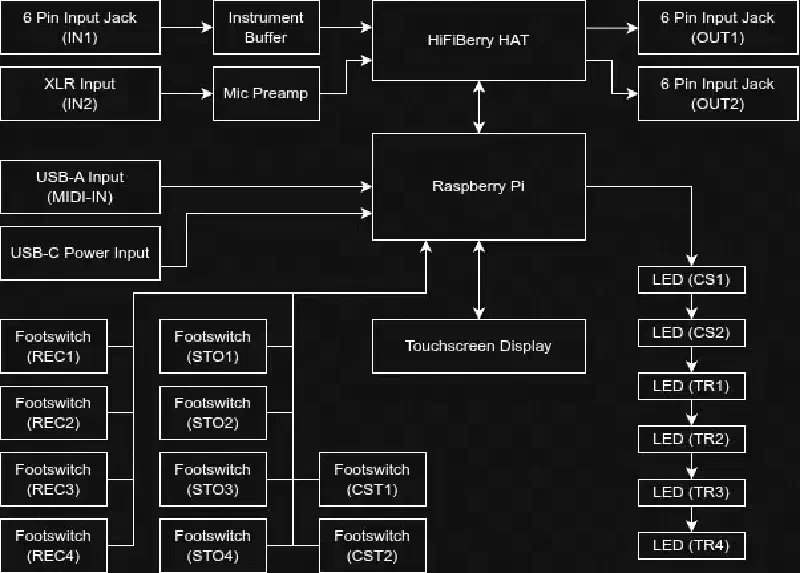
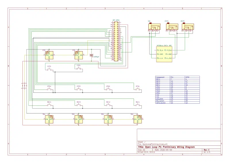
For the initial build before desigining the microphone preamp or instrument buffer circuit, I put together this wiring diagram for reference using KiCAD. I had to be careful with which GPIOs were used by the HiFiBerry and which were not, and also decided to use the SPI pin for controlling the LEDs as using a PWM pin may apparently interefere with the audio as well. The input and right output jacks are wired to the raspberry pi as well so we can do mixing the output to mono in software instead of just summing the signals, and can detect when an instrument is actually connected.
Enclosure#
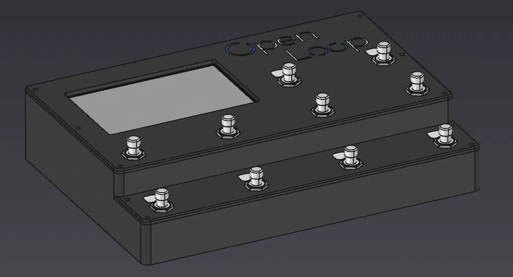
A large standard cast aluminum enclosure could be used for this build, but I’d like to design it to be more compact with two “stair steps” for the play and stop switches. For the prototype I’m going to 3D print it in PETG, and use conductive tape if noise is an issue.
Draft#
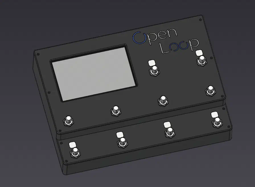
To get an idea for the dimensions, layout, and assembly process I quickly made a draft model in FreeCAD.
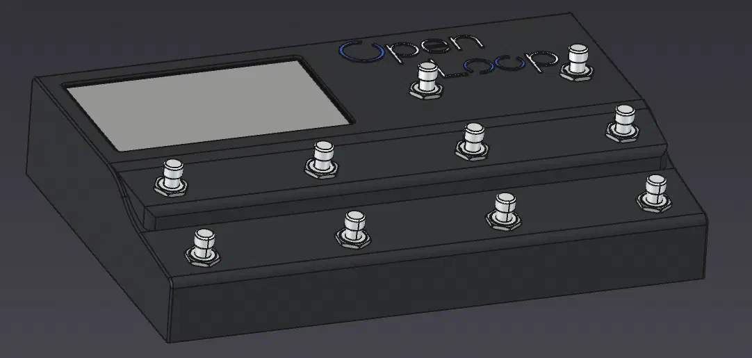
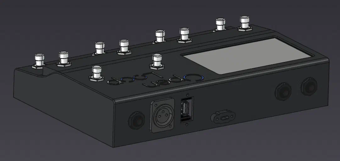
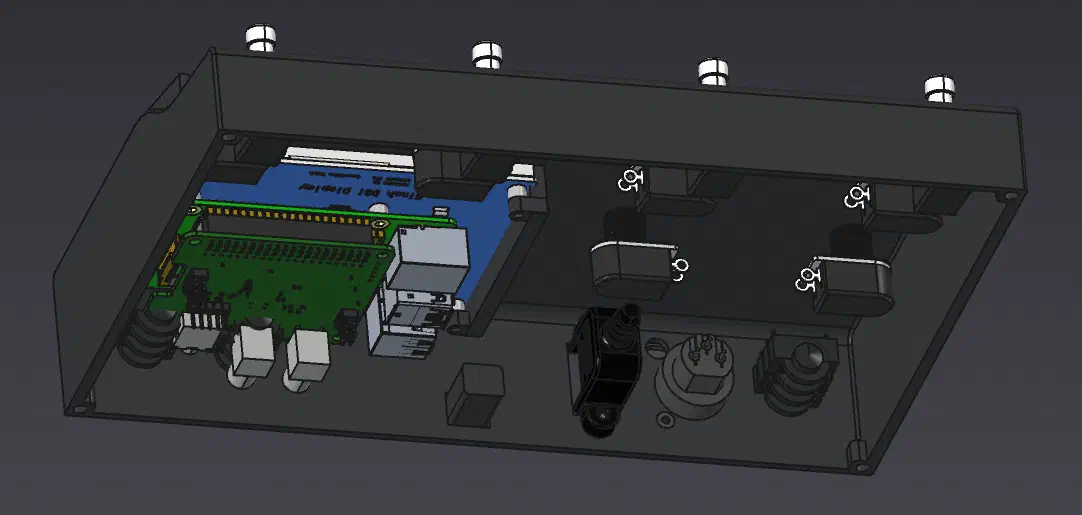
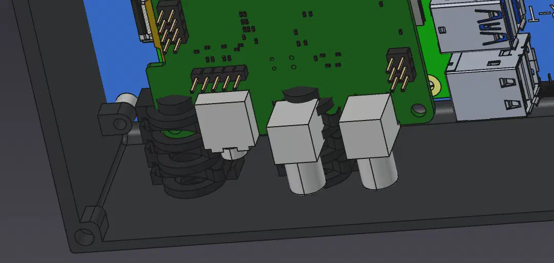
This model looked good in terms of the screen and switch placements but there were many things that wouldn’t practically work, such as: the audio output placements interfering with the Raspberry Pi, the structure being unoptimized for 3D printing, and the screen mounting being basically un-assemblable.
Model P1#
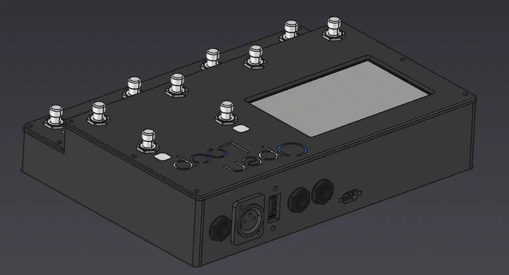
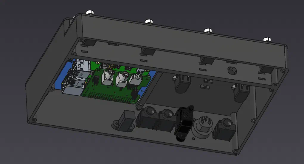
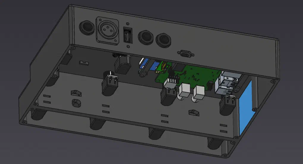
Using these lessons from the draft model, I reconsidered out the design to optimize for 3D printing and assembly, as well as adding LED indicator mounts, and zip tie mounts for cable routing.
To avoid overhangs/support and to make maintenance easier the top, bottom, and back surfaces would be seperate parts printed flat on the build plate and assembled to a base.
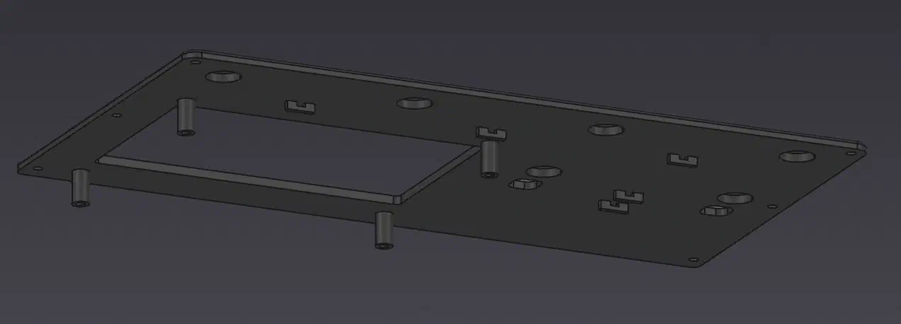
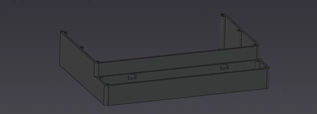
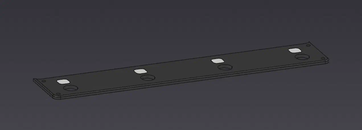
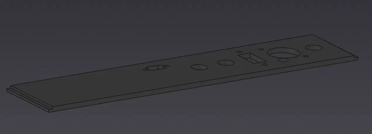
For the LEDs, I made thin white “windows” that the light will shine though, and mounts that would be secured using zip ties for ease of disassembly.
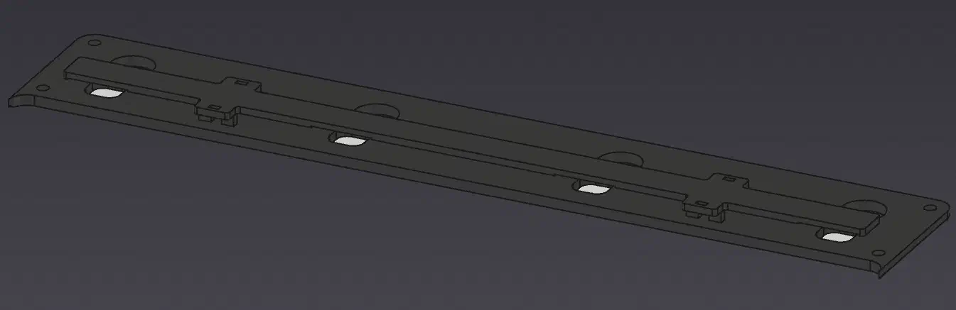
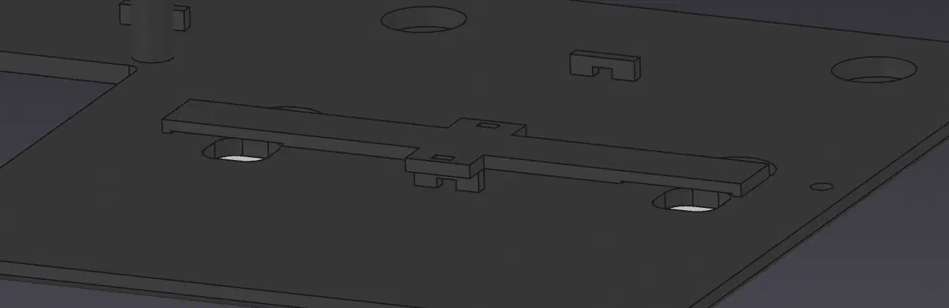
The screen will be mounted with a set of mounting bars that connect to standoffs on both the base and the screen, allowing the whole electronics assembly able to be attached or detached with a few screws.
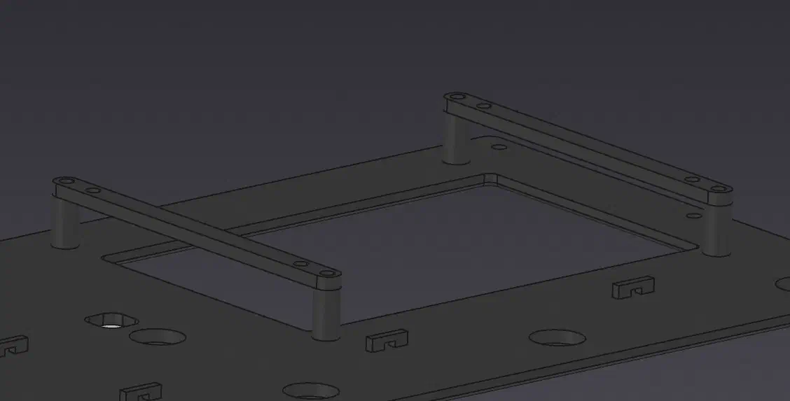
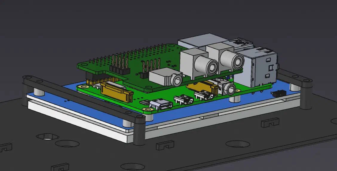
Making the model more robust this time using some techniques from my assembly tips video, I created an assembly and made adjustments to ensure that everything would fit together correctly.
BOM#
This spreadsheet details all the used hardware and the costs. (Embedded spreadsheet display to be fixed)
Hardware Build#
To have a working platform to test the software on during development, I first assembled an initial version of the pedal with just one instrument input and no buffer or microphone input yet.
Wiring and Assembly#
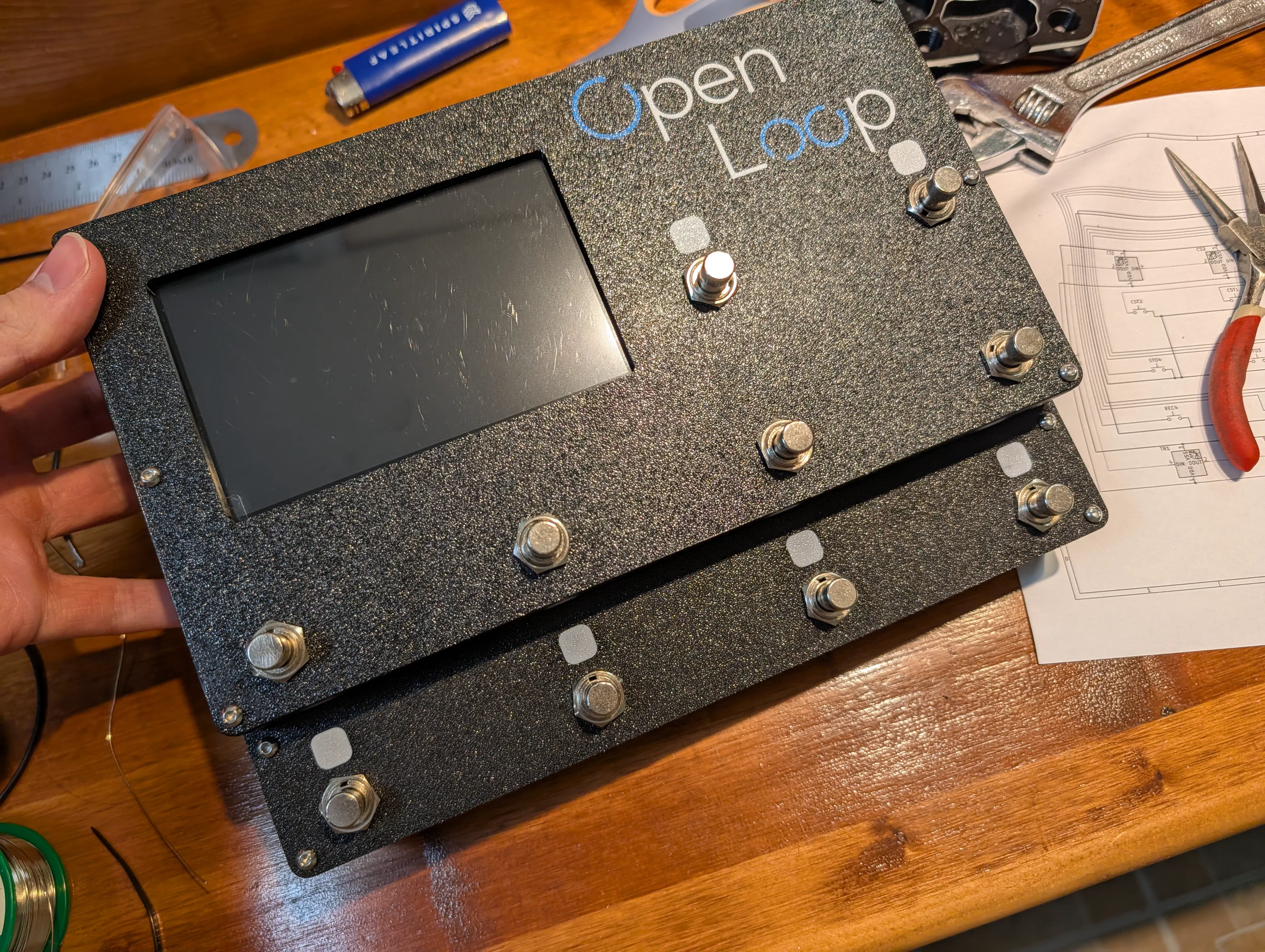
After ensuring the electronics worked correctly and some small test fit prints it was time for the first prototype assembly.
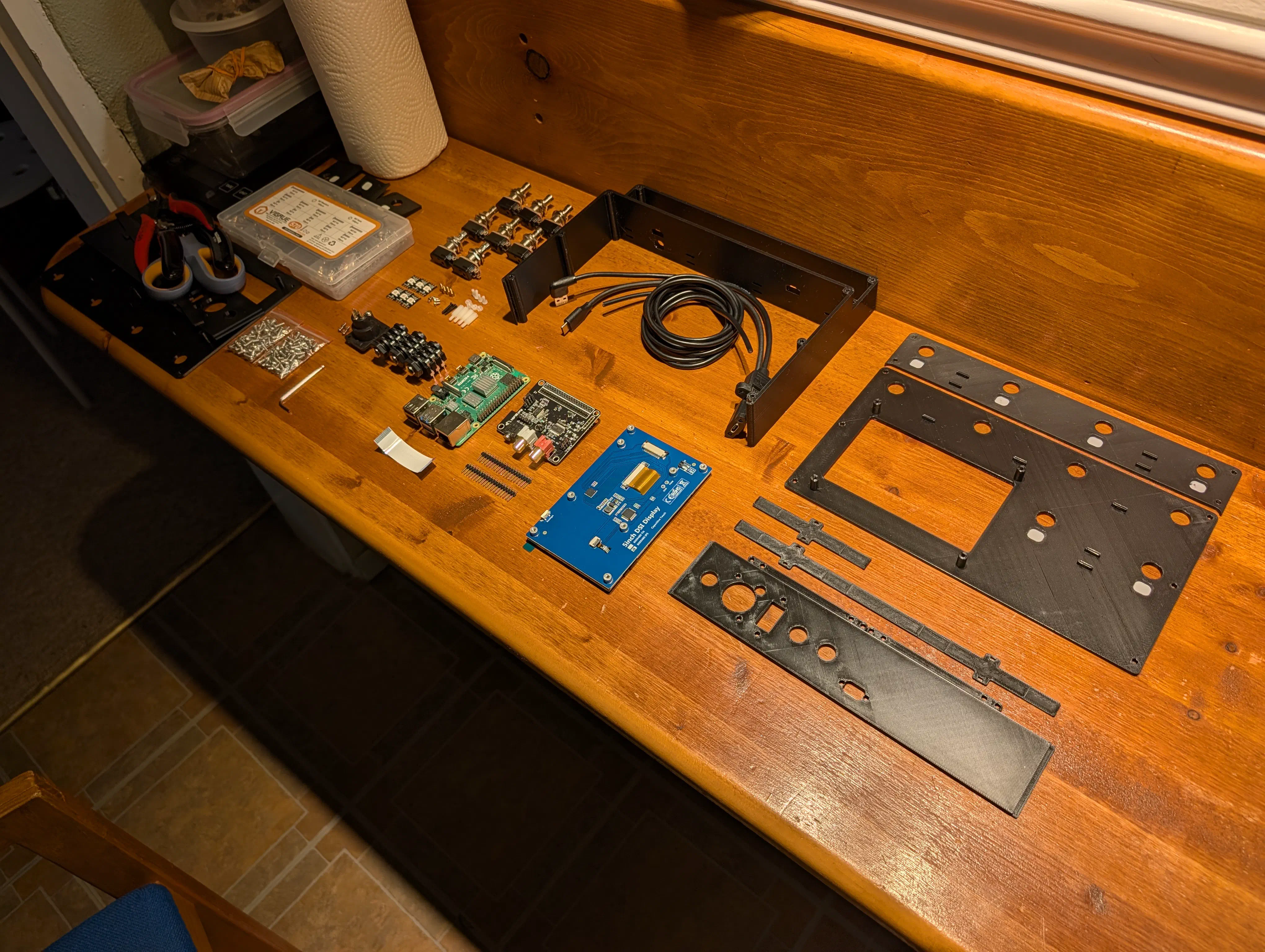
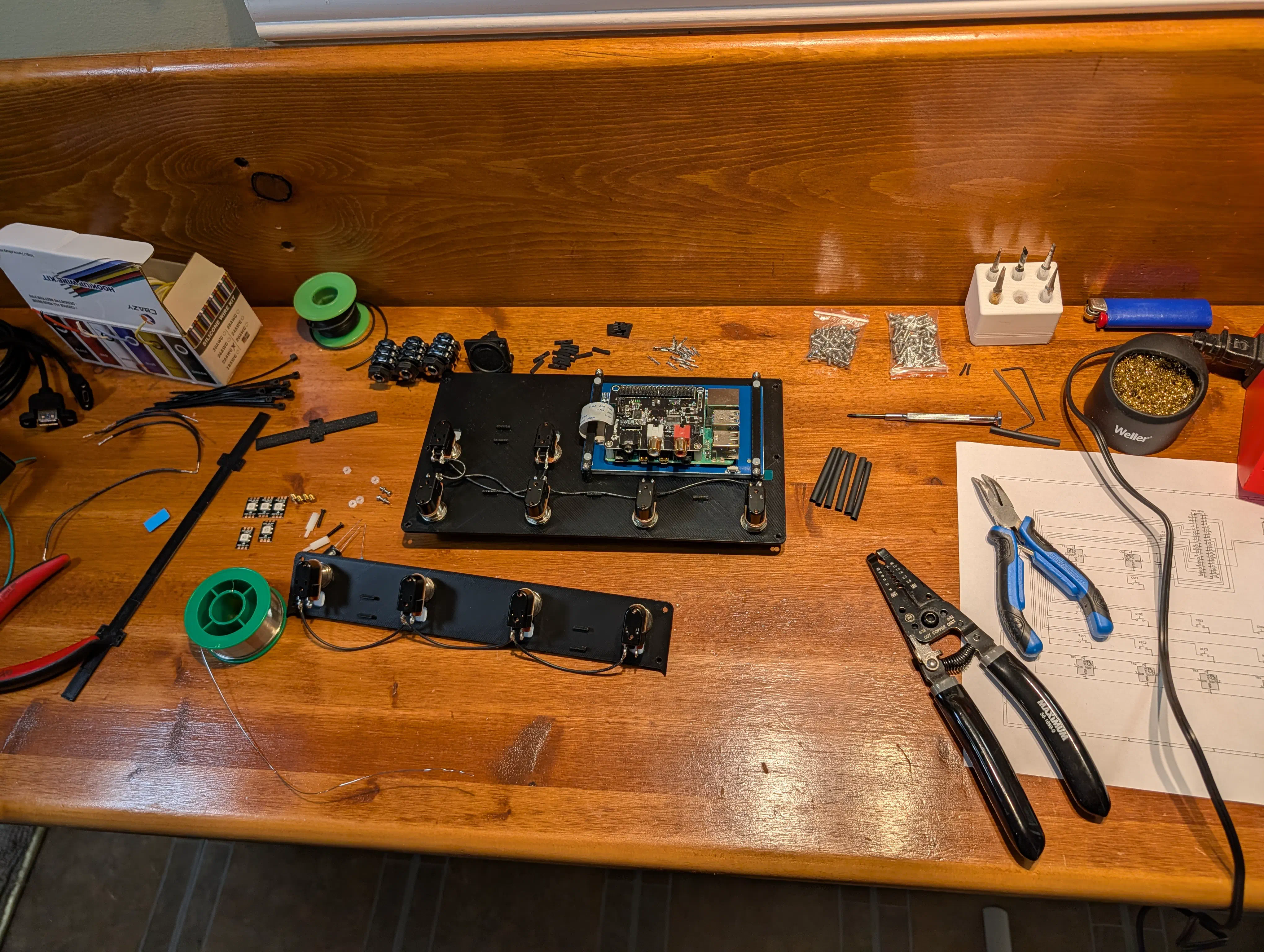
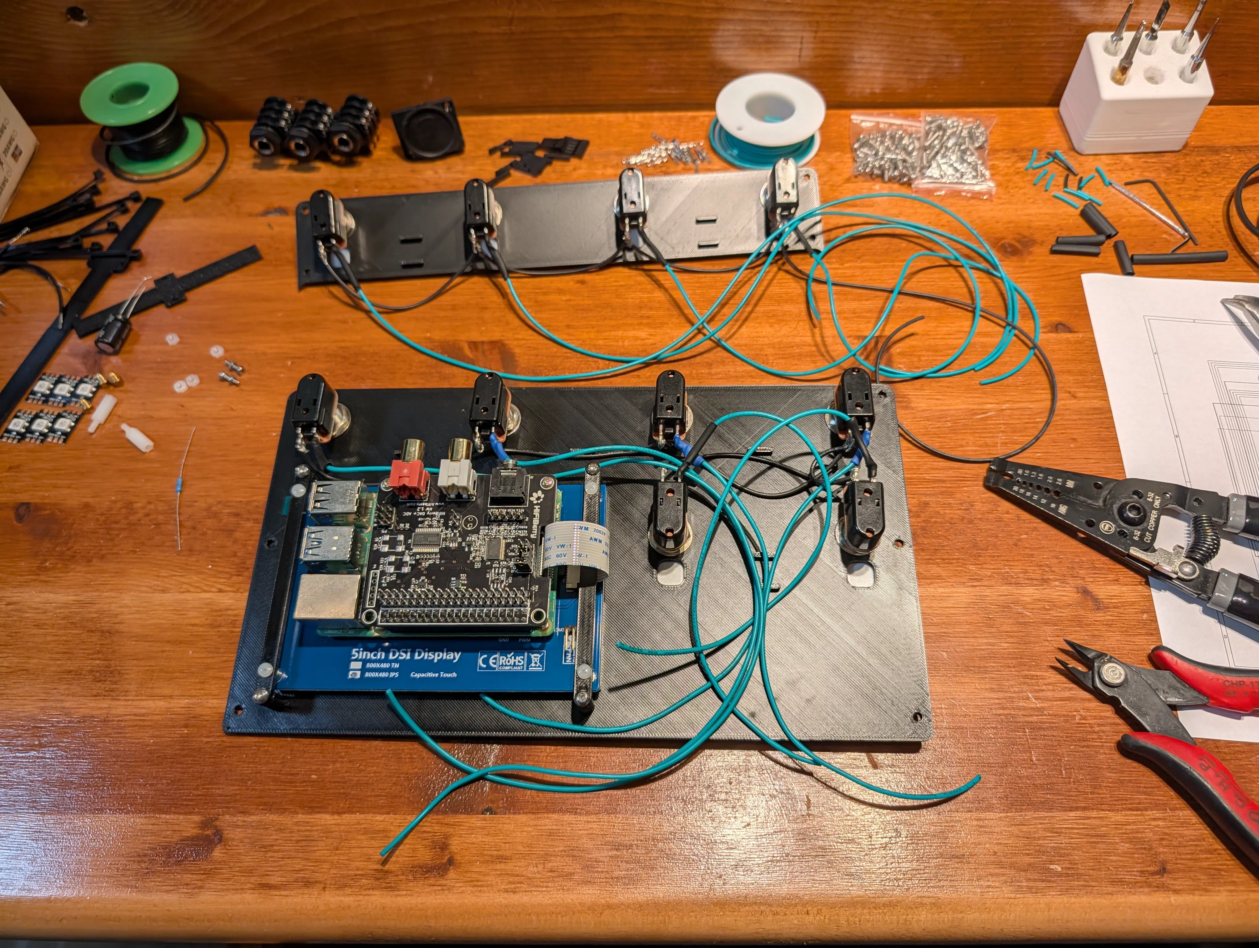
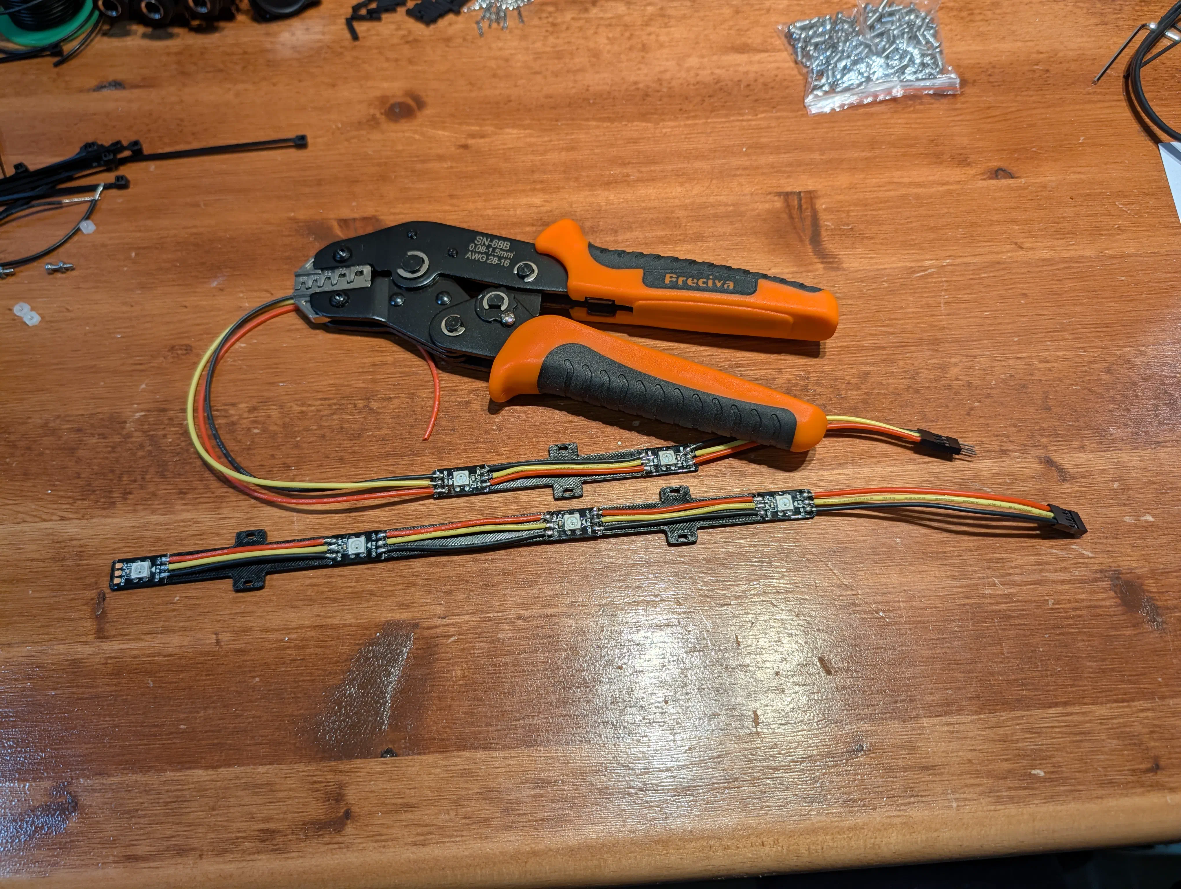
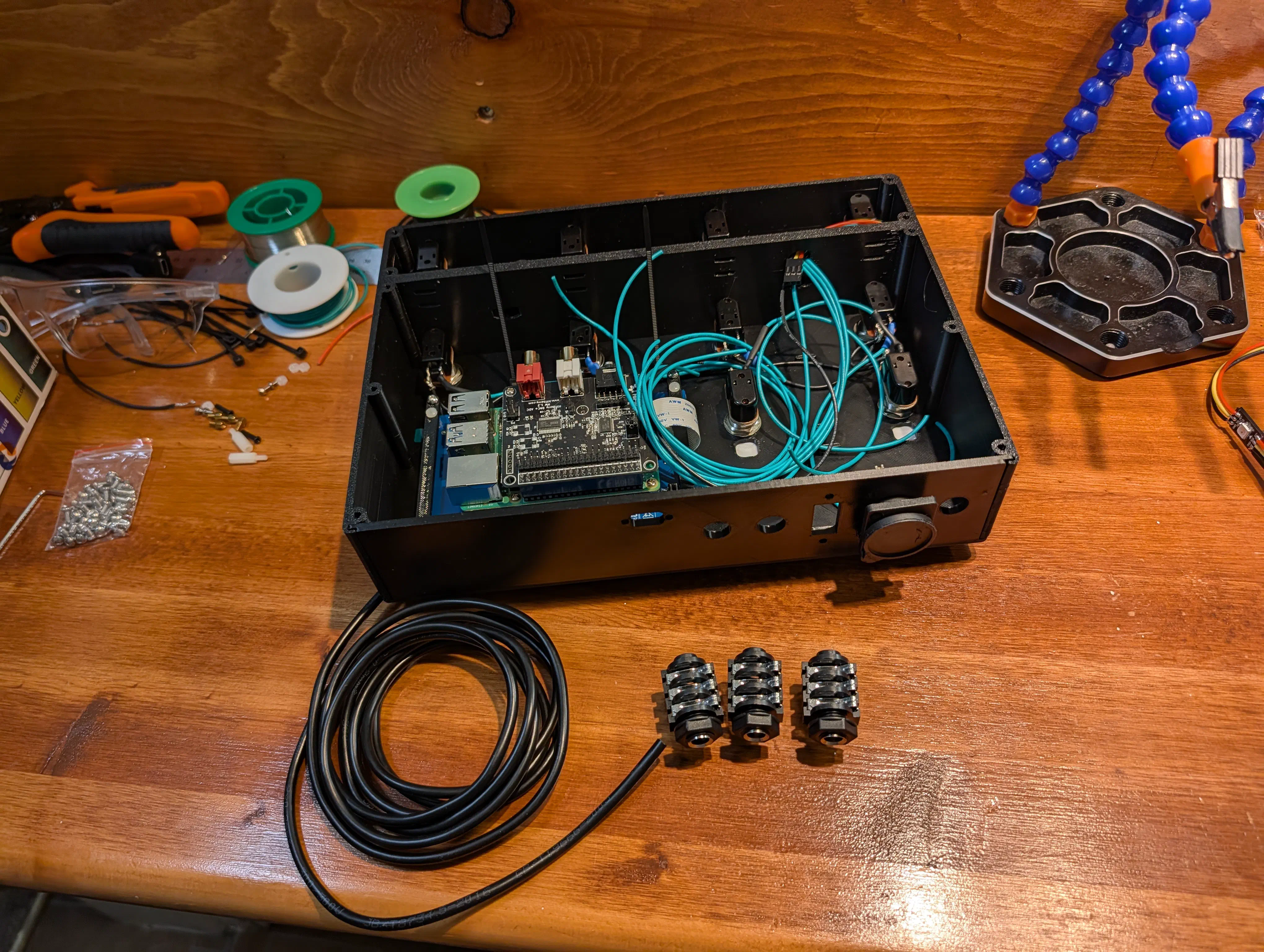
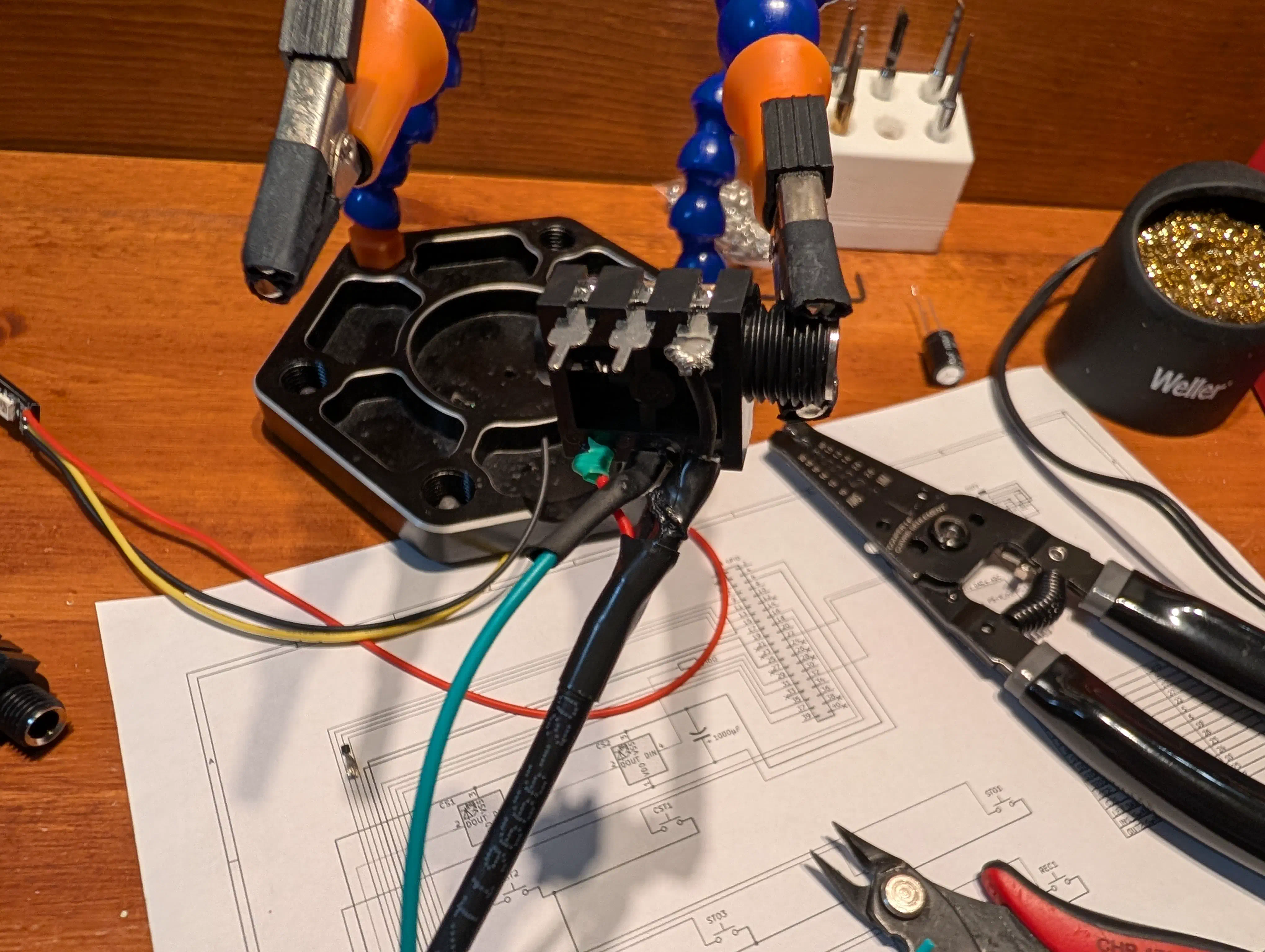
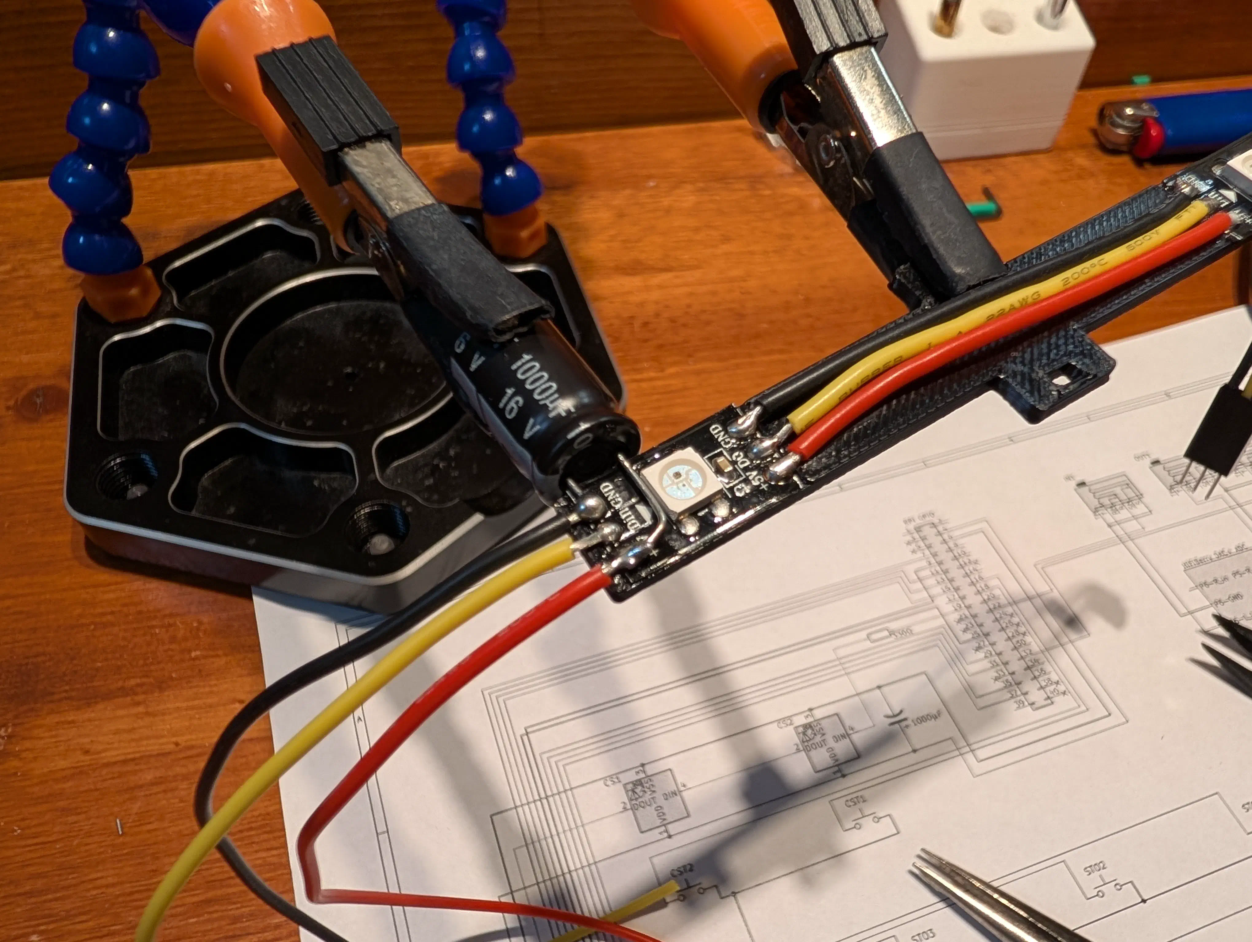
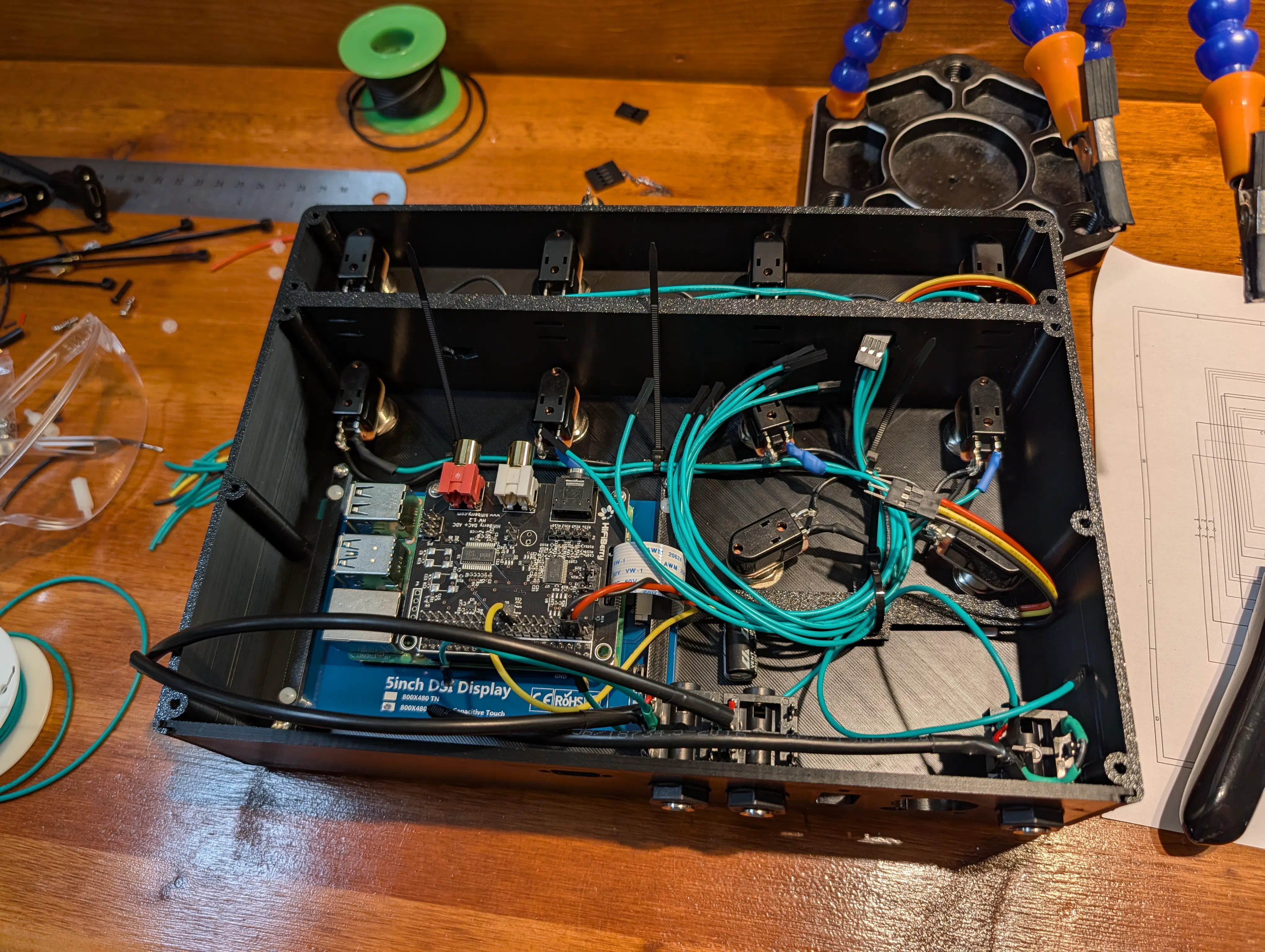
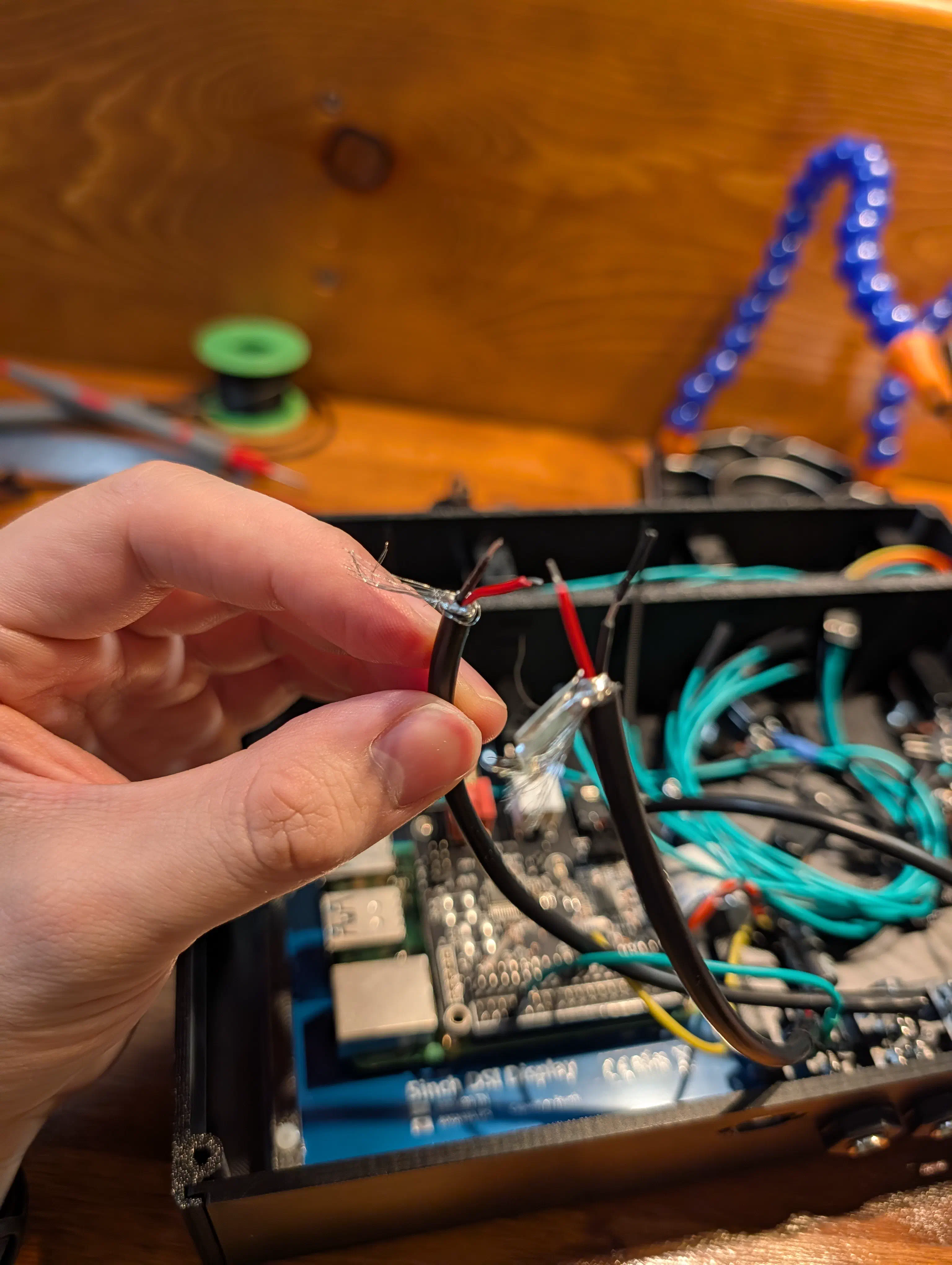
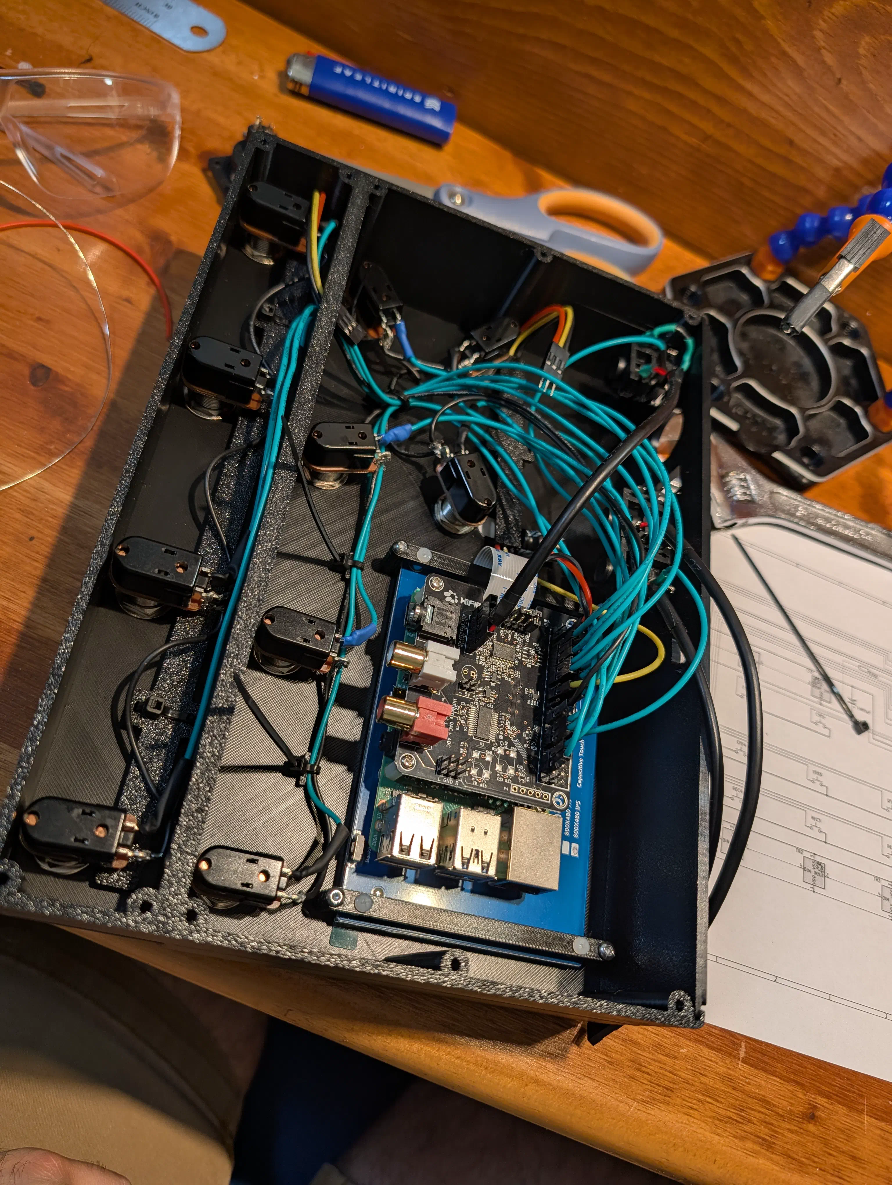
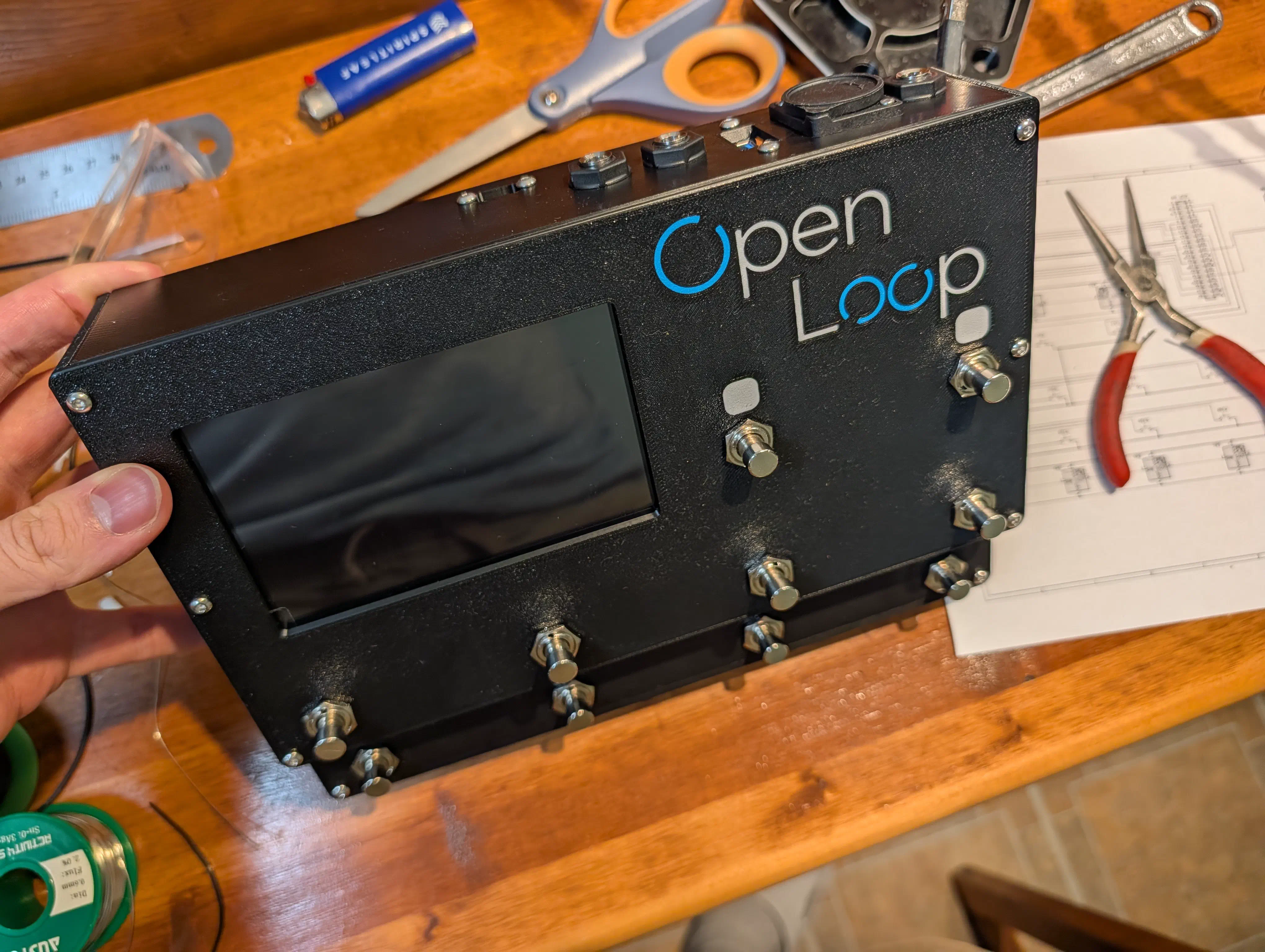
This went pretty smoothly, though it was much more time consuming than expected. In future versions of this pedal PCB mounting the components and simply connecting some boards together will save a lot of time spent making cables and soldering.
Switch, Screen, and LED Demo#
After getting my development environment set up I got Gemini to throw me together a simple test program to display the switch states and control the LEDs with the switches, validating that all the physical hardware (sans sound card) was working properly.
Software#
OS Setup#
To get the Raspberry Pi processing audio with as low latency as possible, a few modifications to the base Raspberry Pi Lite OS are required. Using the lite OS strips away the unnecessary desktop environment while a UI can still be implemented using the DRM (Direct Rendering Manager). As mentioned earlier in the electronics section, low latency audio without any xruns takes a bit of extra setup. To ensure that we get that smooth glitch free audio, we apply the PREEMPT_RT Linux kernel patch. This allows you to set higher priority tasks and ensures that they will interrupt lower priority ones when needed, in this case ensuring that the audio server never stutters due to the UI or other processes locking up the cpu.
(Step by step instructions may be moved to a separate article)
Pi Set Up Instructions
These instructions apply to a fresh install of Raspbian OS Lite (Debian 13 Trixie) as of May 2026. Your mileage may vary.
To do this, open a shell on the raspberry pi via ssh or by connecting the display and keyboard.
Building the Kernel#
Install some prerequisites and download the kernel source
sudo apt update
sudo apt install git bc bison flex libssl-dev make libncurses5-dev build-essential
cd ~
git clone --depth=1 --branch rpi-6.12.y https://github.com/raspberrypi/linux
cd linux
Then generate the config file and open the configuration menu
make bcm2711_defconfig
make menuconfig
In this menu navigate to General setup -> Preemption Model -> Fully Preemptible Kernel (Real-Time)
Then save and exit
Edit the config file to make the version clear.
Set CONFIG_LOCALVERSION to “-v8-rt” or similar
Build the Kernel with
make -j4 Image.gz modules dtbsChill for the ~2 hours it takes to compile, then install the kernel modules
sudo make modules_installCopy the kernel and device tree files into the boot partition
sudo cp arch/arm64/boot/Image.gz /boot/firmware/kernel_rt.img
sudo cp arch/arm64/boot/dts/broadcom/*.dtb /boot/firmware/
sudo cp arch/arm64/boot/dts/overlays/*.dtbo /boot/firmware/overlays/
sudo cp arch/arm64/boot/dts/overlays/README /boot/firmware/overlays/
Then edit /boot/firmware/config.txt and make the following changes:
- Find the
[all]block and addkernel=kernel_rt.imgright below it - Add
dtoverlay=hifiberry-dacplusadcto enable the HiFiBerry drivers - Disable the onboard audio by changing
dtparam=audio=onto off
Now reboot the pi and check that the real-time kernel is running with uname -a
Real Time Privileges#
Now that the kernel is set up we need to enable our system to allow more priority to be given to the audio server, and to prevent memory from ever being moved from RAM to the SD card.
Add the user to the audio group
sudo usermod -a -G audio $USERCreate a audio.conf file with sudo nano /etc/security/limits.d/audio.conf and place the following in and save
@audio   -  rtprio     95
@audio   -  memlock    unlimited
Check by rebooting and checking ulimit -l and ulimit -r
These should be “unlimited” and “95”
Startup Config#
Set the pi to auto login on boot by using sudo raspi-config and navigating to System Options -> Auto Login and enabling auto login.
Software Architecture#
To implement all the planned features in this pedal, the following programs and software tools will be used.
- Custom logic: C# and .NET SDK
- UI: Avalonia UI
- Audio/MIDI Routing: PipeWire
- Loop Engine: Sooperlooper
- Effects: guitarix
- Synthesizer: FluidSynth
- Drums: Hydrogen
When powered on the pedal should load straight into the custom UI with all the required engines, engines, services, and routing spinning up automatically in the background.
Audio Routing#
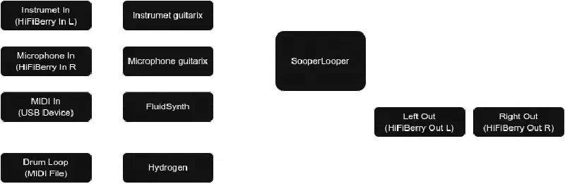
This diagram shows the plan to use Pipewire to route the audio sources through effects, MIDI through FluidSynth, and everything through the loop engine. Drum loops will play straight from files and get routed directly to the output (or get mixed somehow first?)
Audio Server#
For the audio server I will be using PipeWire. It will result in slightly more latency than pure JACK Audio (still within the acceptable range), but the benefit is more flexible and reliable audio routing as well as ease of development.
To set up PipeWire first install the needed packages sudo apt install pipewire pipewire-audio-client-libraries pipewire-jack
Make a local config in the home directory
mkdir -p ~/.config/pipewire
cp /usr/share/pipewire/pipewire.conf ~/.config/pipewire/
and edit the file. Uncomment and modify the following lines in the context.properties section
default.clock.rate          = 48000
default.clock.allowed-rates = [ 48000 ]
default.clock.quantum       = 64
default.clock.min-quantum   = 64
default.clock.max-quantum   = 64
Then set PipeWire to start automatically on boot
systemctl --user enable --now pipewire pipewire-pulse wireplumberSet the mix levels by opening alsamixer then hitting f6 and selecting the HiFiBerry card. Set “Digital” to -3.5db gain.
Exit and save the settings with sudo alsactl store
Making Sounds#
jack-keyboard fluidsynth -a jack -j -m jack /usr/share/sounds/sf2/FluidR3_GM.sf2 slgui -l 2
pw-link jack-keyboard:midi_out fluidsynth-midi:midi_00
pw-link fluidsynth-midi:left sooperlooper:common_in_1
pw-link fluidsynth-midi:right sooperlooper:common_in_2
pw-link sooperlooper:common_out_1 alsa_output.pci-0000_00_1f.3-platform-skl_hda_dsp_generic.HiFi__hw_sofhdadsp__sink:playback_FL
pw-link sooperlooper:common_out_2 alsa_output.pci-0000_00_1f.3-platform-skl_hda_dsp_generic.HiFi__hw_sofhdadsp__sink:playback_FR
Mic Inputs:
pw-link alsa_input.pci-0000_00_1f.3-platform-skl_hda_dsp_generic.HiFi__hw_sofhdadsp_6__source:capture_FL sooperlooper:common_in_1
pw-link alsa_input.pci-0000_00_1f.3-platform-skl_hda_dsp_generic.HiFi__hw_sofhdadsp_6__source:capture_FR sooperlooper:common_in_2Effects#
For built-in effects, I’m going to be using the open-source Guitarix and LSP (Linux Studio Plugins). The plan is to use the LV2 plugin format which inherently decouples the audio processing and UI, allowing the custom pedal UI to control the effects through OSC or MIDI. To use these plugins a host is required to manage and provide an interface to interact with them. For this I will be using mod-host from the MOD Project which handles the routing of multiple effects internally and provides one simple input and output for PipeWire/JACK.
Software Required Config#
To run a C# Avalonia application, the dotnet runtime and some other required libraries must be installed.
wget https://packages.microsoft.com/config/debian/13/packages-microsoft-prod.deb -O packages-microsoft-prod.deb
sudo dpkg -i packages-microsoft-prod.deb
rm packages-microsoft-prod.deb

sudo apt-get update && \
  sudo apt-get install -y aspnetcore-runtime-10.0
sudo apt update
sudo apt upgrade
sudo reboot
sudo apt install libgbm1 libgl1-mesa-dri libinput10SPI Configuration#
You must ensure SPI is enabled on your Raspberry Pi. You can do this by running sudo raspi-config, navigating to Interface Options -> SPI, and enabling it.