Intro#
This article documents the process of designing and building my most recent side project: a small CNC router capable of cutting aluminum. It was intended as a one-off with materials I happened to have on hand, but if you are working on a similar project or are just interested in the process of a project like this then keep reading as I cover all my design decisions and the troubleshooting process on the journey from blank page to working machine. If you’d like to view all resources associated with this project including the CAD files, see Resources.
Background#
I was inspired to start this project when I was given some scrapped lead screws and linear rails, as well as a deal on a good amount of aluminum extrusion. Already owning most of the needed components, and wanting the ability to make my own wood and aluminum parts, I decided to take on the challenge of designing and building this machine.
Before this project I had some experience working with CNC routers, but this was my first time designing a 3 axis machine myself. This means there were many learning opportunities along the way.
Design#
Requirements#
Before opening up CAD, I first listed out my requirements to design around. It would have to:
- Use the parts I have on hand. For the sake of cost, and to make use of my ever growing stockpile.
- Be able to cut aluminum, to give the option of making stronger parts for future projects.
- Fit in a small space, smaller than a square meter. I would love to have a large table sized router but just don’t have the space for one right now.
Design Decisions#
Using What Ya Got#
I first took stock of what usable parts I already owned:
- 200 mm linear rails with guides
- High quality but questionable condition 380mm ball screws
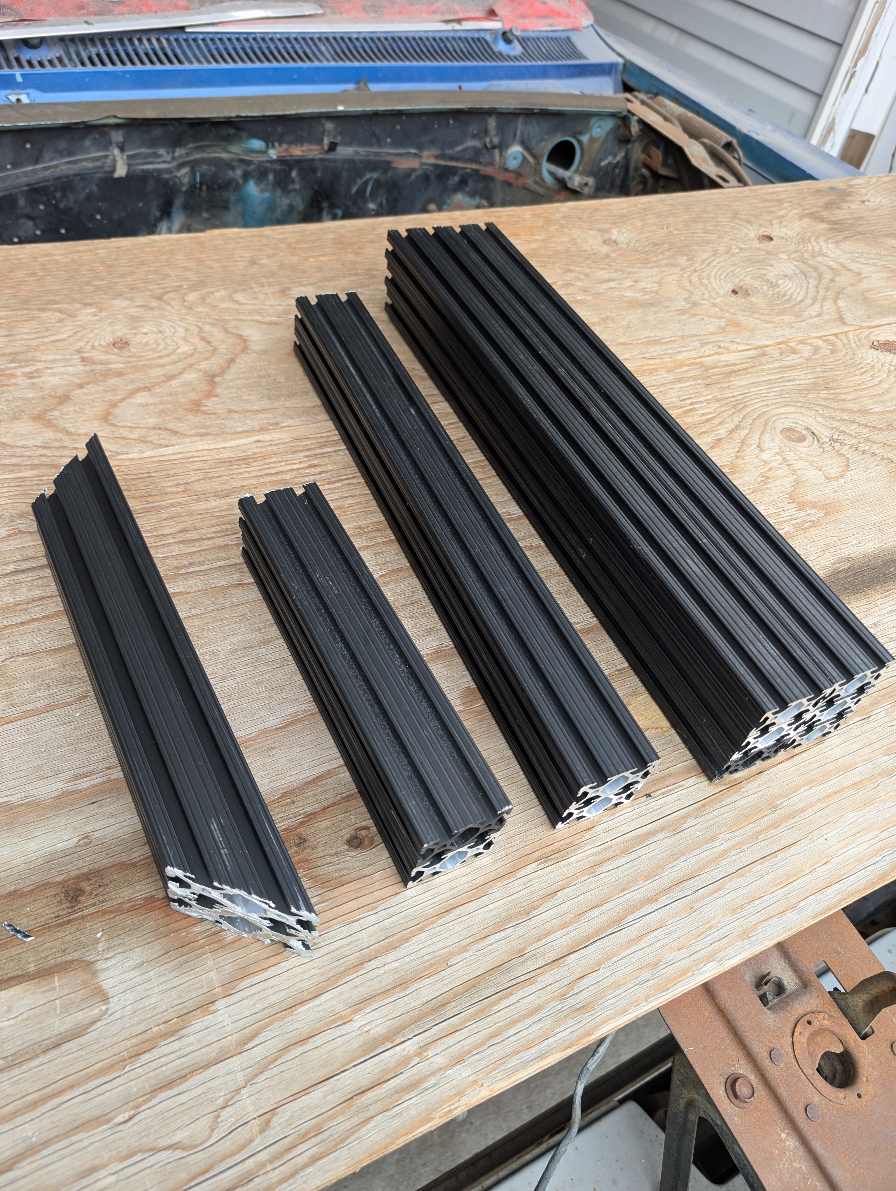
- 1020 (1x2") aluminum extrusion
- 2x NEMA 17 stepper motors
- An arduino and TMC2208 stepper motor drivers
- A 24V power supply
- A 3D printer (to make parts, not the printer itself)
Using all these parts saved hundreds of dollars, but limiting myself to them also introduced some challenges:
- Would butting the 200mm linear rails up against each other allow the guides to run smoothly? How would I align them to be parallel, and how would I mount them to the 1020 extrusion?
- The ball screws were for a custom application. How would I modify them to work in this case? If damaged are they repairable?
- Would the stepper motors and drivers provide enough torque?
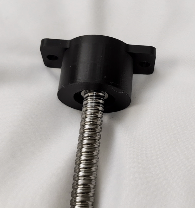
- How will the ball screws be secured? Can the stepper drivers take the axial load or are custom bearing blocks needed?
Before going ahead with the design, I did some research to answer these as best I could.
Asking some co-workers and reading some forum posts, I was satisfied that butting the rails up against each other should work for a reasonable amount of time as long as they were properly aligned. As for mounting, I couldn’t find T nuts that would work for the linear rails and for 1" extrusion, so I decided to order some 2020 T nuts and after trying them found that they should work.
One of the ball screws felt like it was jamming in one direction, but after working it in a little bit it seemed fine (foreshadowing?) Either way they seemed functional enough and would be easy to make shorter with an angle grinder.
To estimate if my NEMA 17 stepper motors would work I ballparked the amount of force they would produce with my 4mm pitch ball screws, and compared it to the numbers from this paper I found that included an analysis of aluminum milling forces. It found the cutting forces to range between 40N and 120N. Using the 42Ncm stall torque rating of the motors I’m using, the 4mm pitch of the ball screws, and estimating a 70% efficiency, and plugging those into this formula: \(F = \frac{2\pi \cdot T \cdot \eta}{L}\) I found that the motors should produce around 461.8N.
$$F = \frac{2\pi \times 0.42\,\text{Nm} \times 0.70}{0.004\,\text{m}} = 461.8\,\text{N}$$This seemed workable with a large margin of safety, though if you’re questioning if the stall torque rating is what should be used when cutting happens at speed.. You’d be right, and there will be more on that later.
I also realized that most off the shelf ball screws came with bearing blocks that took the axial load - the lengthwise pressure on the shaft, whereas my naked ball screws didn’t. If the motor bearings themselves could take this load it would be convenient, and it seemed like some other budget routers also used hanging ball/lead screws without support. For more confidence, I used this chart posted on a machinist forum post from someone asking a similar question.
Assuming my motors were similar, it seemed like the 40-120N would be well within the normal bearing life range for an average of 2000mm/min (500rpm with a pitch of 4mm/rotation) so I didn’t worry about designing load bearing bearing blocks.
Cutting Metal#
In doing research on what would be required for the machine to cut aluminum, I found that rigidity would be the deciding factor on if it would be capable. Now I wouldn’t know where to start on analyzing the actual force being applied to a complex assembly like this and what would bend, so I decided to look for examples of hobby level routers that can cut metal, and how they were constructed.
I looked at many machines that used similar materials to what I had, such as Ivan Miranda’s which used a combo of aluminum framing, linear rails, and 3D printed parts to cut even steel. So I figured my materials should be workable. I decided to use PLA for the printed parts as it is actually both stiffer and stronger than other common materials, at least until it snaps, but that’s a good thing for rigidity. One potential issue is that PLA can creep - deform over time under constant tension. But that would be a problem for future me.
UPDATE: Future me here. Around 10 months since first setting up the router all the hardware used to fasten PLA did need another ~1/8 turn re-torque, but nothing shifted or had any issues after this adjustment. Worst case the heat set inserts may eventually need to be re-set deeper if they pull out after a few re-torques but the PLA gets a thumbs up for now.
One notable choice was whether to go with a fixed or moving gantry. With a moving gantry the entire X axis moves to produce Y movement, whereas with a fixed gantry the bed moves instead.
I ultimately decided on a fixed gantry. Although this reduces the working area in the Y direction, I was more confident in the rigidity of a fixed X axis mounted with extrusion, as opposed to 3D printed parts coupling the x axis to a gantry.
Dimensions and Layout#
Size wise, I wanted this to be portable and able to fit on a desk. I was okay with a relatively small build volume, so I looked for similar sized projects for inspiration and found the open source MilkCr8 CNC project.
Referencing the available CAD model was very helpful for planning the initial layout. Knowing that the linear rail spacing and positioning worked well on that machine at least was reassuring while completing the rest of the design from scratch. Although this project is intended as a one-off, the files used for this project are available in the CAD section as well in case you want to open them up in FreeCAD for similar inspiration.
Electronics#
To power and control the machine a few different components are needed.
Requirements:
- A controller - receives G-code instructions and translates them to motor driver signals. Also connects any switches, coolant pumps, spindle controllers, or other devices integrated into the machine.
- Motor Drivers - receive directions from the controller and actually provide the power to send the motors to the requested position.
- Stepper or servo motors - can be moved to precise positions with open or closed loop control respectively.
- Power supply - the controller and motor drivers must be given the proper voltage with enough current to operate correctly.
- Spindle or router - the actual cutting tool which can be controlled with a VFD in the case of a spindle or turned on manually with a router.
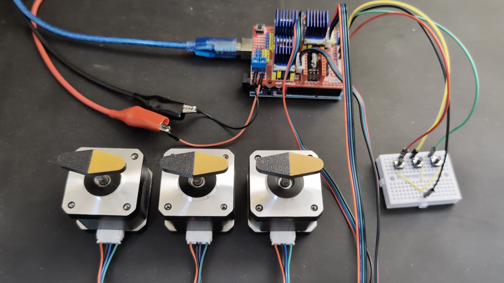
In my case I already owned an arduino with a CNC shield attached, TMC2208 motor drivers, NEMA 17 stepper motors, and a 24V 5A power supply. All that I needed to buy new was the cutting tool.
I decided on buying a router instead of a spindle for both price and simplicity’s sake, but went for a router that takes an ER-11 collet which allows for the use of any generic collet and therefore many different tool sizes.
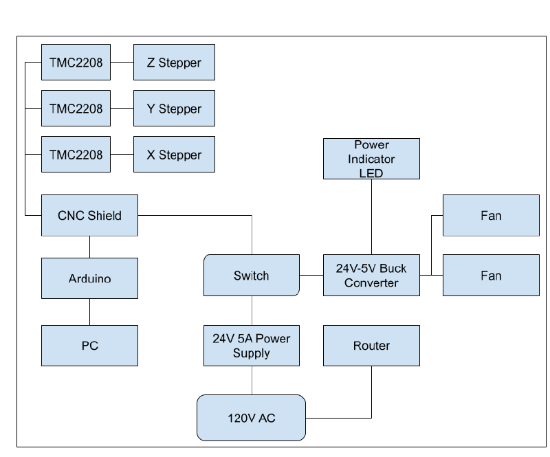
With the components decided upon I made up this simple block diagram to visualize how they would all connect. Figuring the drivers might need some cooling, I integrated some 5V fans and an indicator light as well. While an E-Stop is always a good idea for a machine like this, I made it so the power to the drivers is wired through a large power switch instead, so flicking it off will stop movement no matter what.
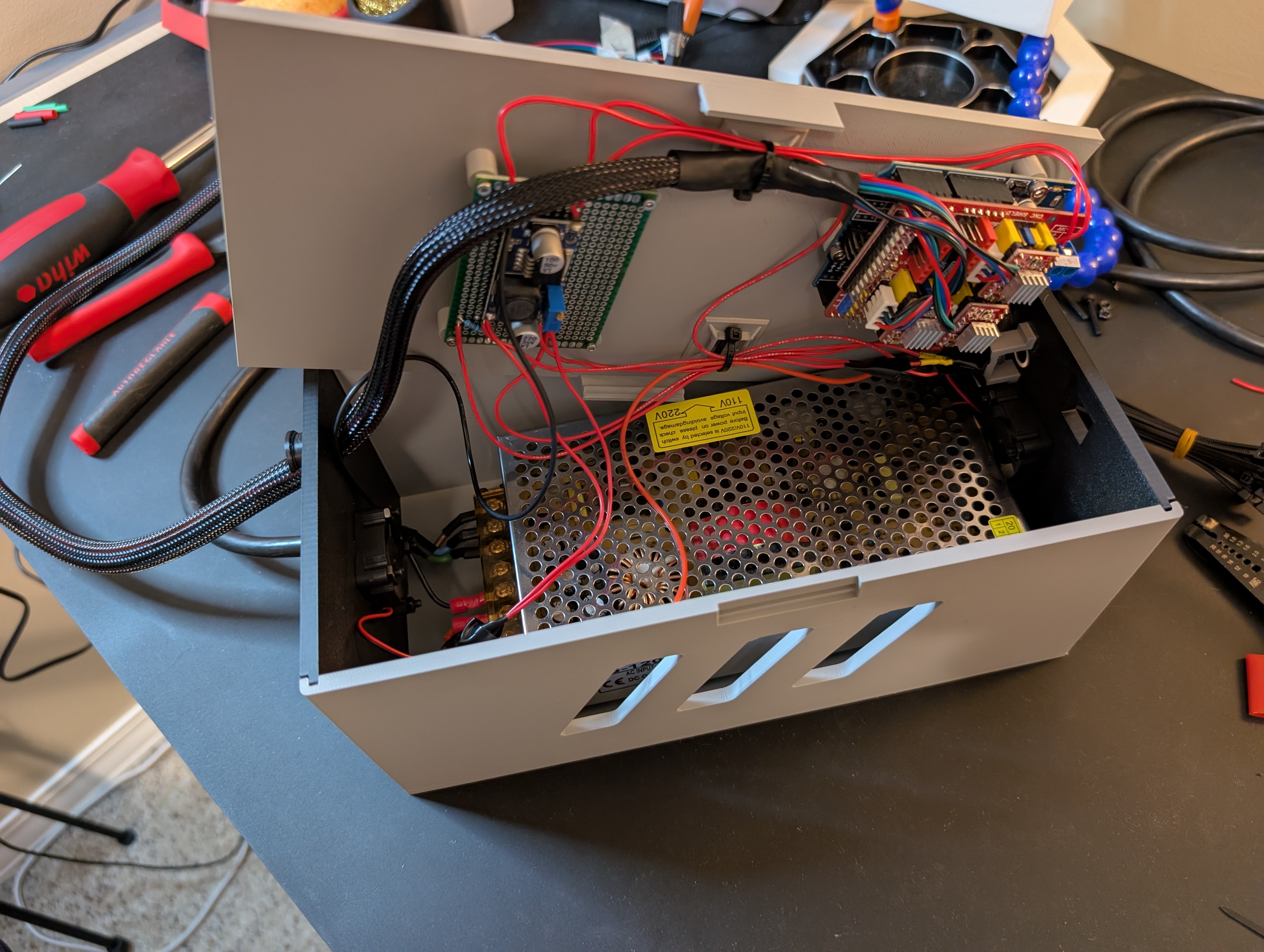
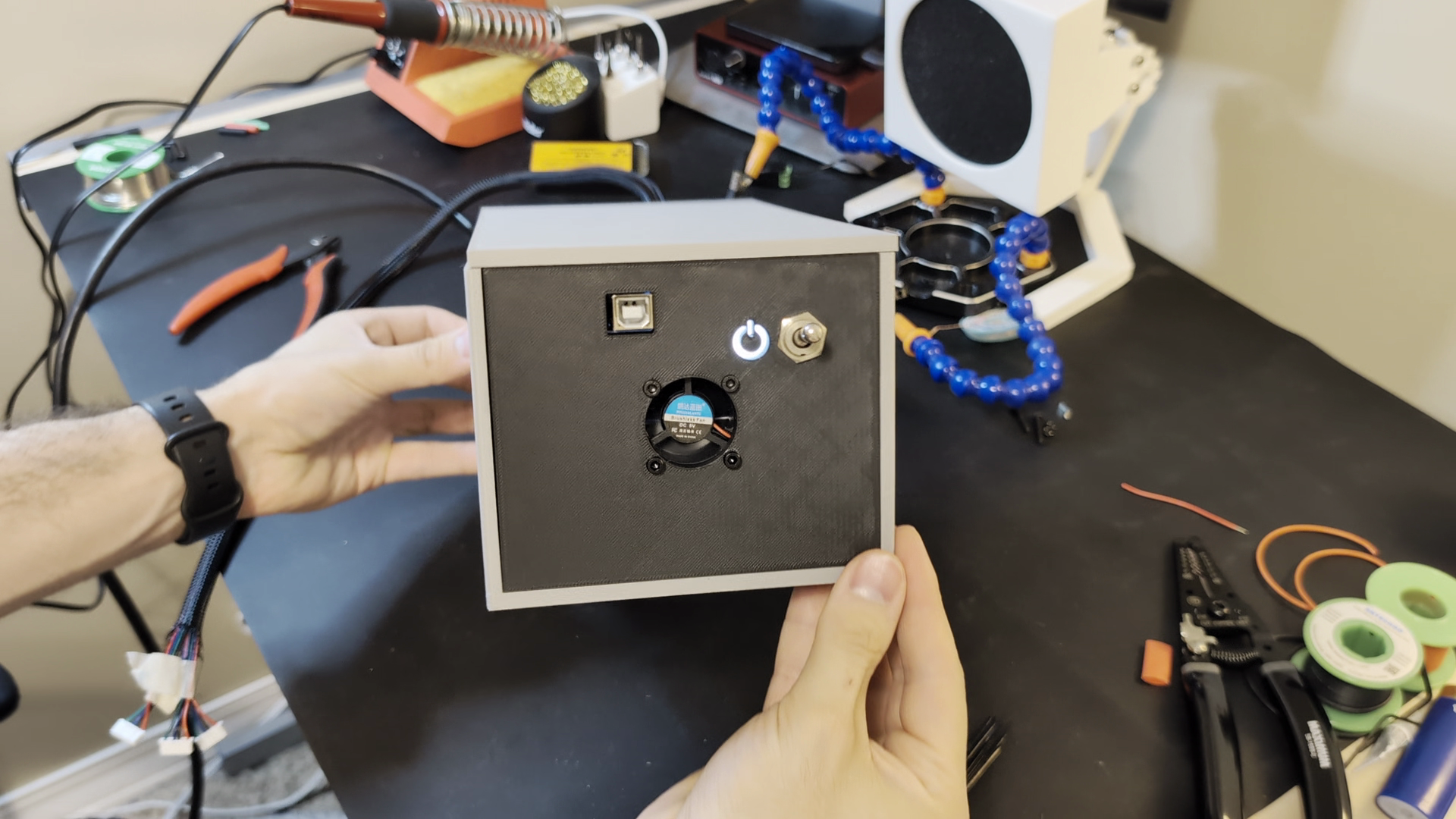
To keep the electronics tidy, safe, and cooled, I also designed an electrical enclosure. This was done later in the process after doing some tests with the electronics setup exposed.
CAD#
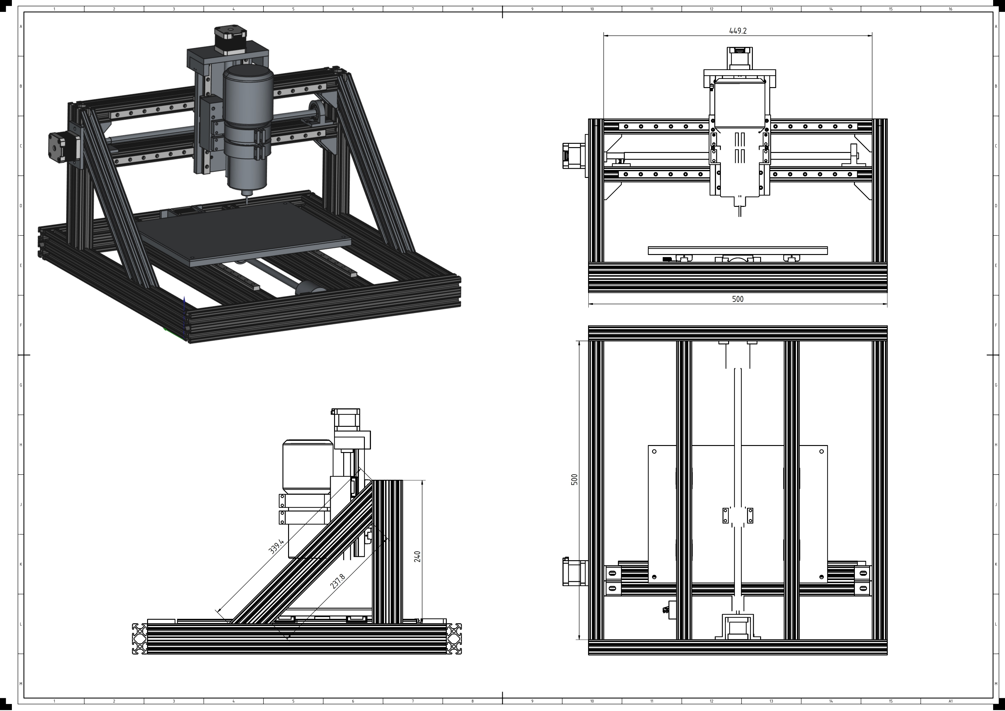
This was the most complex assembly I had made using FreeCAD so far, but the new (at the time) assembly workbench in the 1.0 version of the program made it easier. I posted some videos sharing the assembly knowledge I learned along the way which you can view here: Tutorial, Tips
Knowing this was a one off project, I modelled this just for my own reference and printing purposes. I didn’t model every single detail, but enough to make the parts and know they would fit together. As it turns out modelling every screw would have made this faster, as I did miss a couple hardware fitting details the first time.
This is the model after revisions made later in the process.
If you’d like to check it out in FreeCAD yourself for reference you can download the CAD files here.
Assembly#
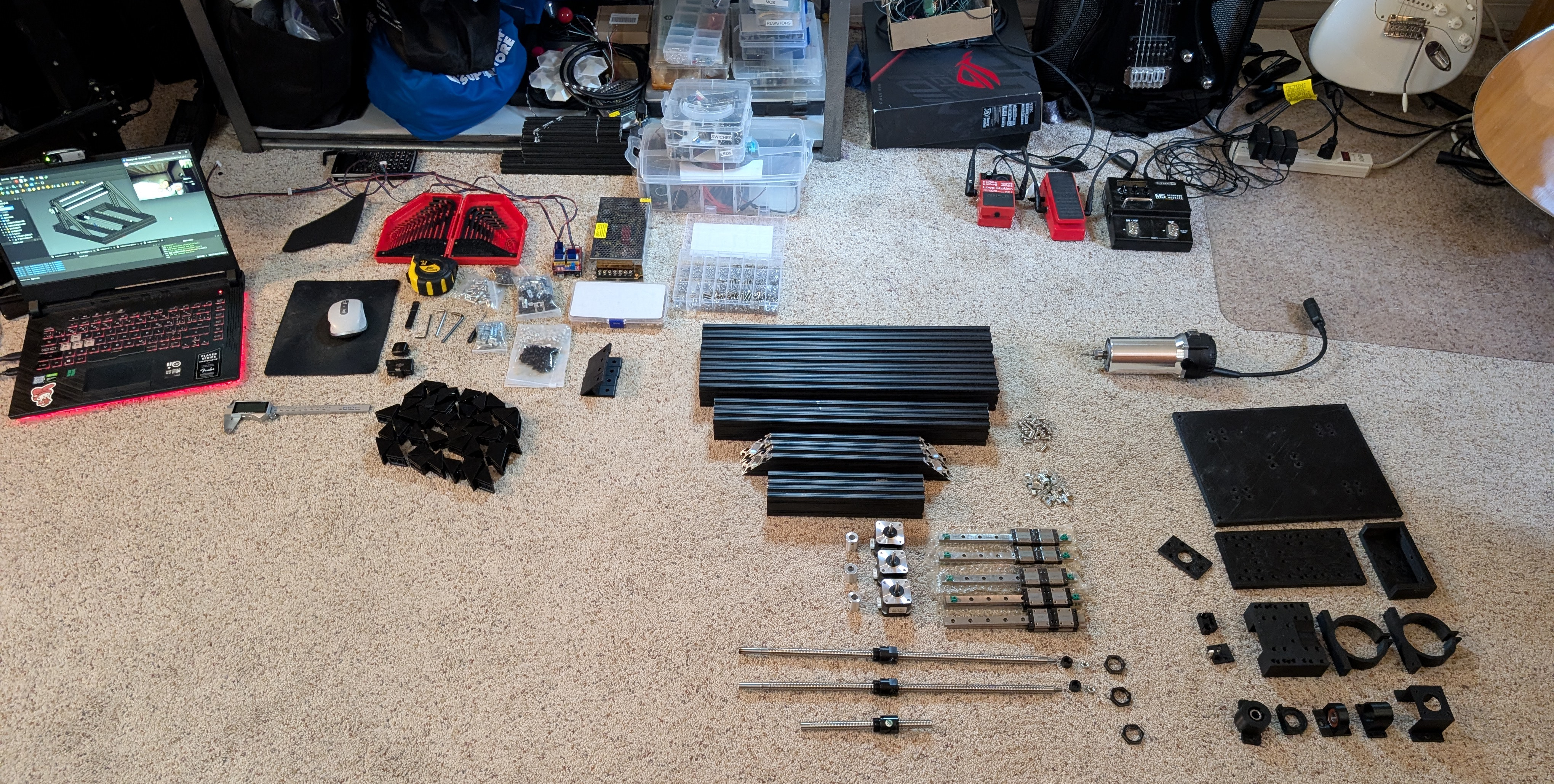
Getting Parts#
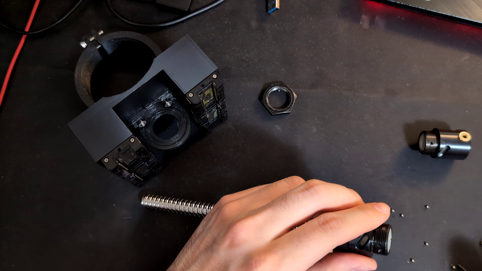
Procuring the parts was pretty easy with a few exceptions. The custom ball screws required M20 x 1mm nuts which were actually pretty hard to find. I ended up having to buy them from a Finning CAT supply store as hardware meant for excavator windshield wipers. I also couldn’t find T-Nuts made for the 1010 imperial sized aluminum extrusion, so I had to order ones made for 2020 and hope for the best. The price of free I guess.
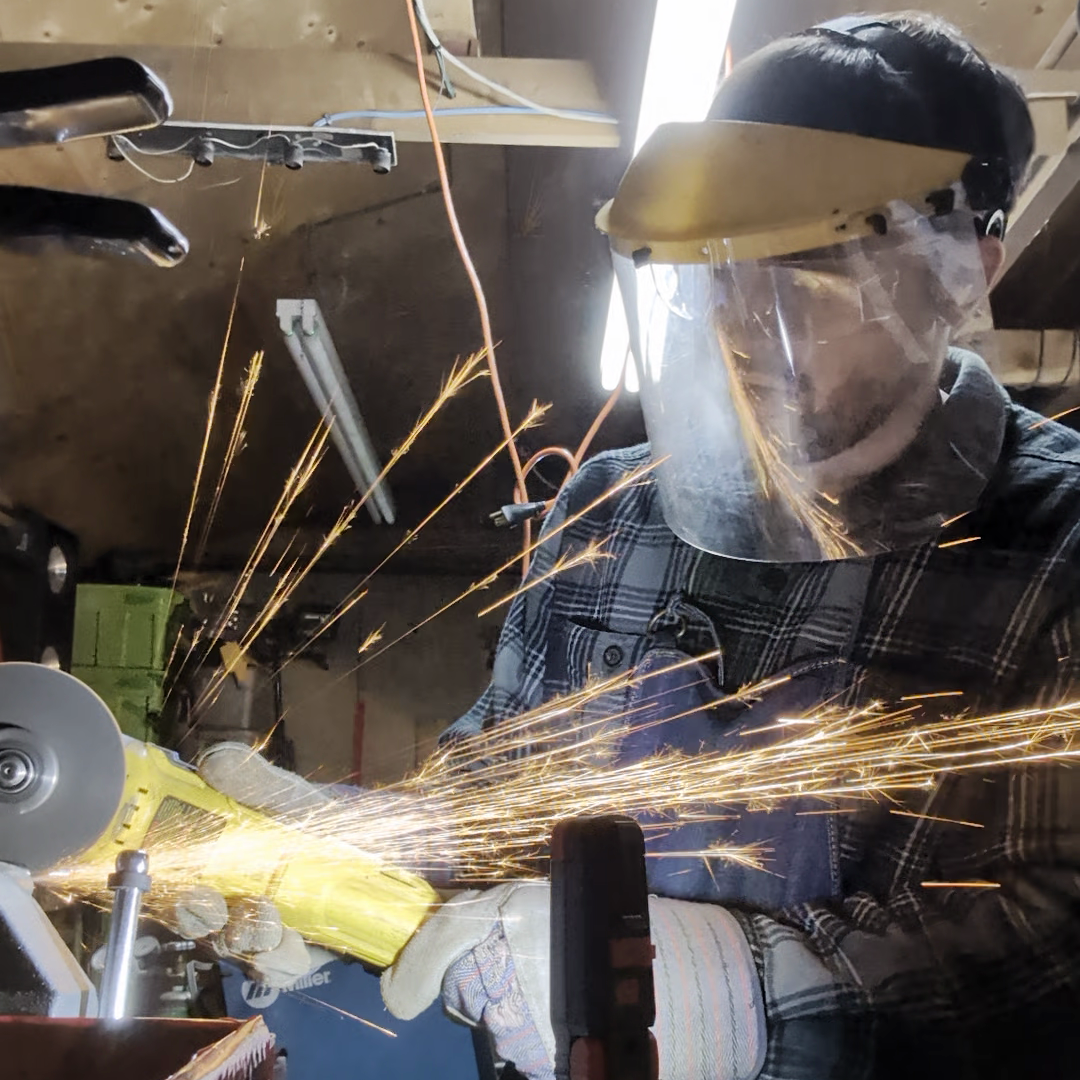
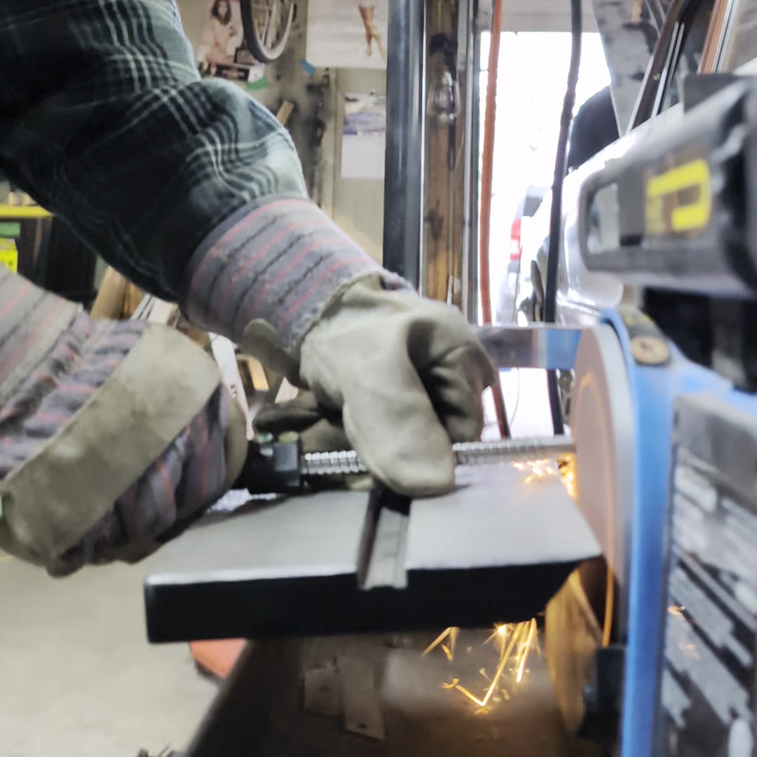
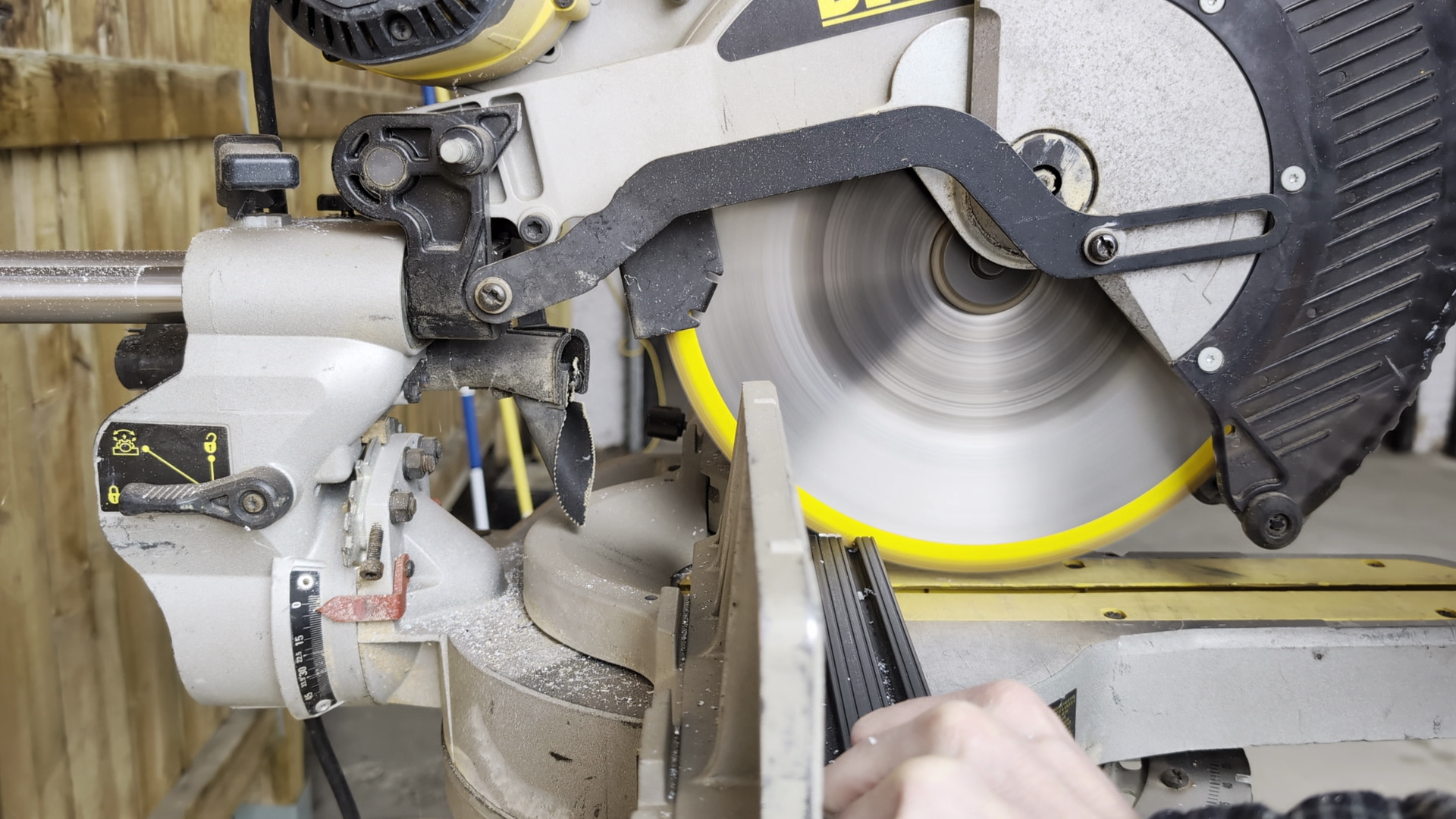
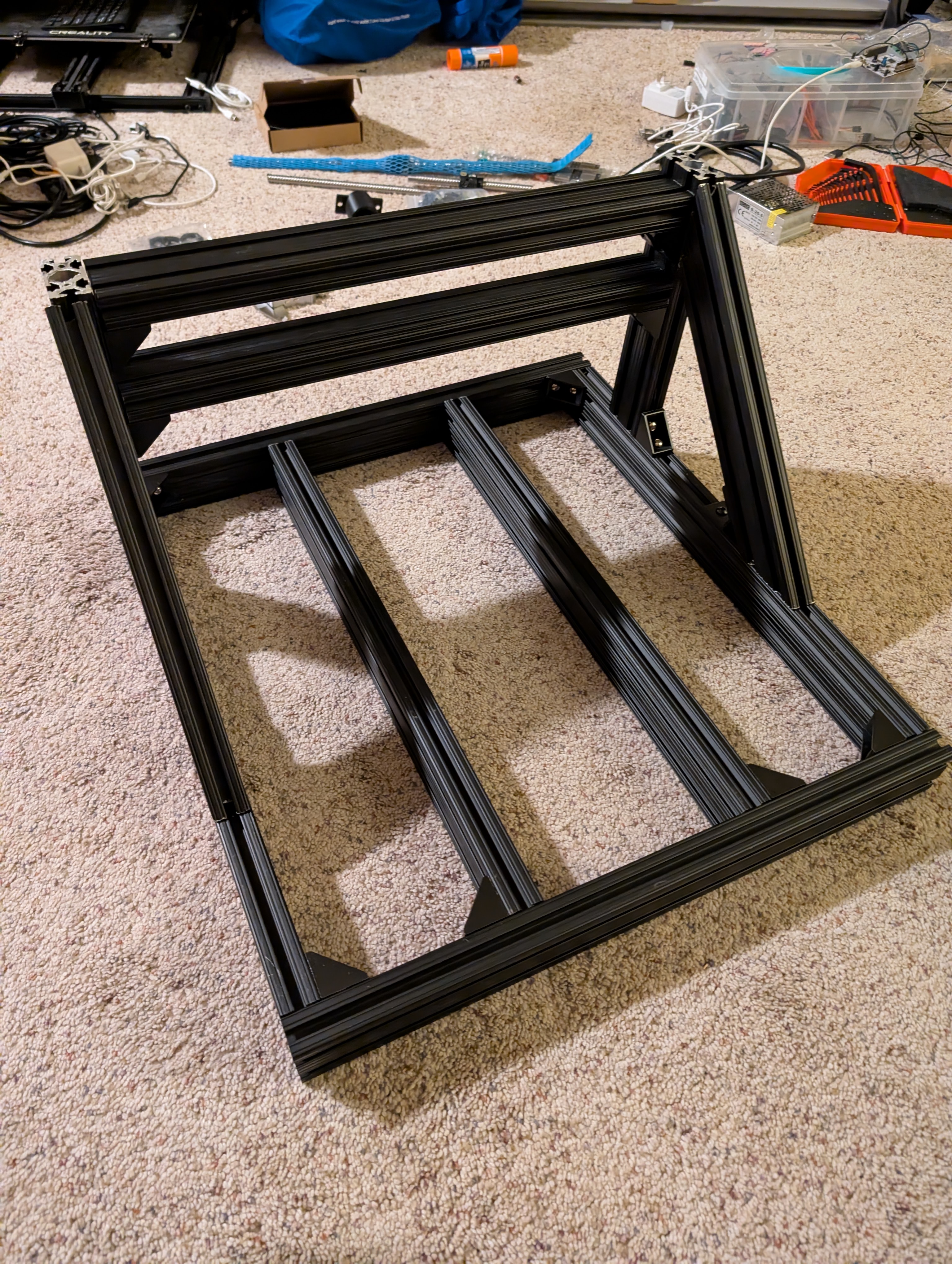
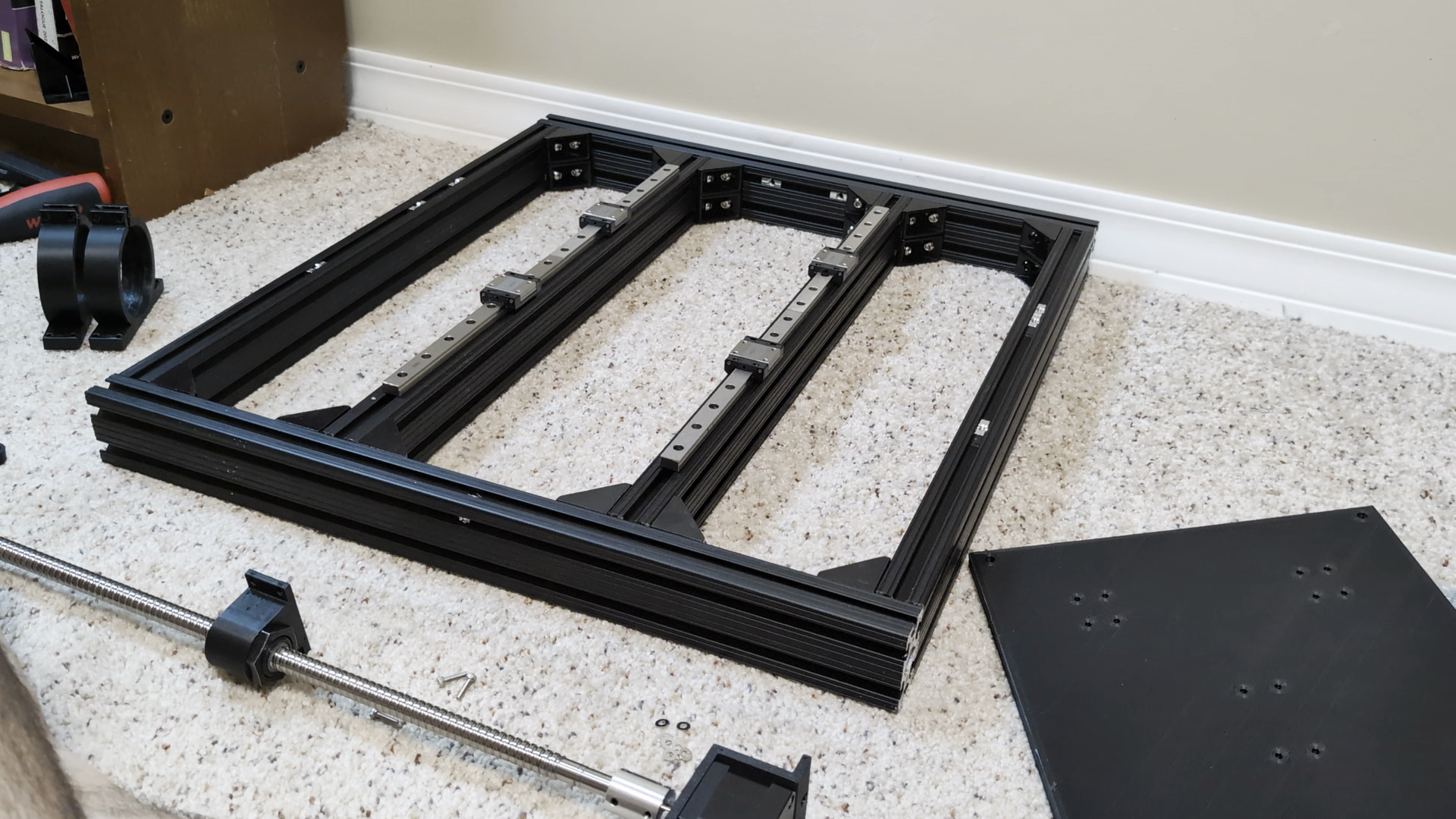
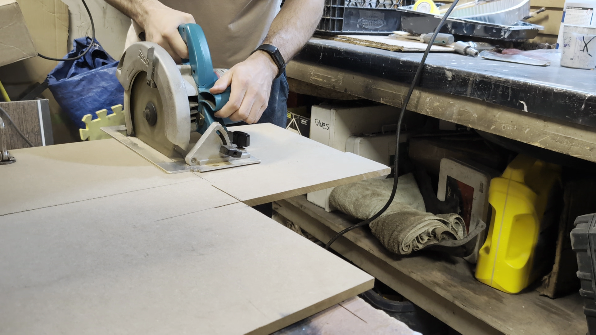
Overall the initial manufacturing/assembly process went smoothly. Just a matter of printing parts, cutting aluminum extrusion and ball screws to size, and making sure the frame fit together.
Electronics Testing#
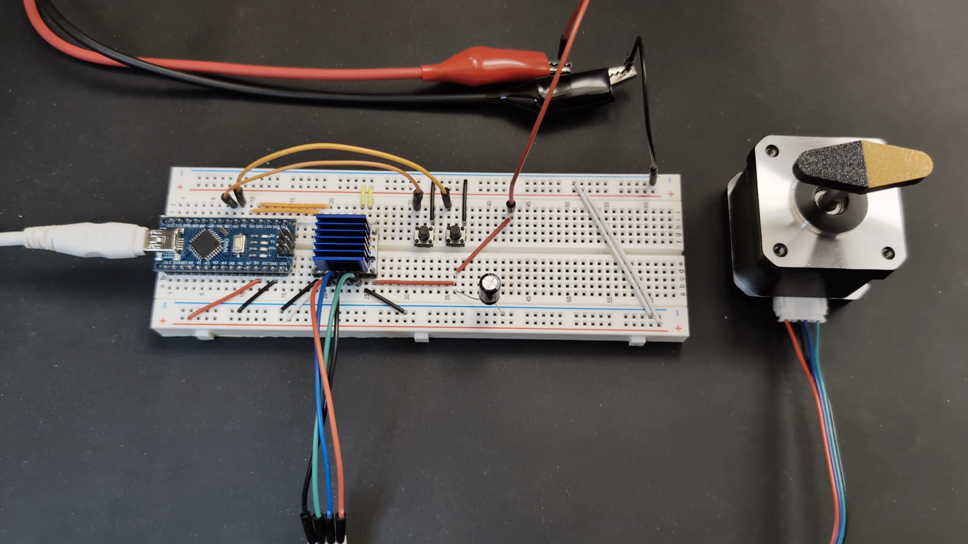
Next I set up and tested the stepper motors, drivers, and controller to ensure everything was working as expected. I used NEMA 17 stepper motors, TMC2208 drivers (more on these later), and an arduino with a CNC shield. I tested the drivers/motors, controller connections, and G-code sending with UGS (Universal G-code Sender) separately. I did this to both learn about how the setup works more thoroughly, and so I would know these are not the issue if a problem comes up later with the whole thing assembled.
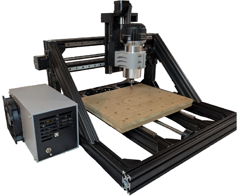
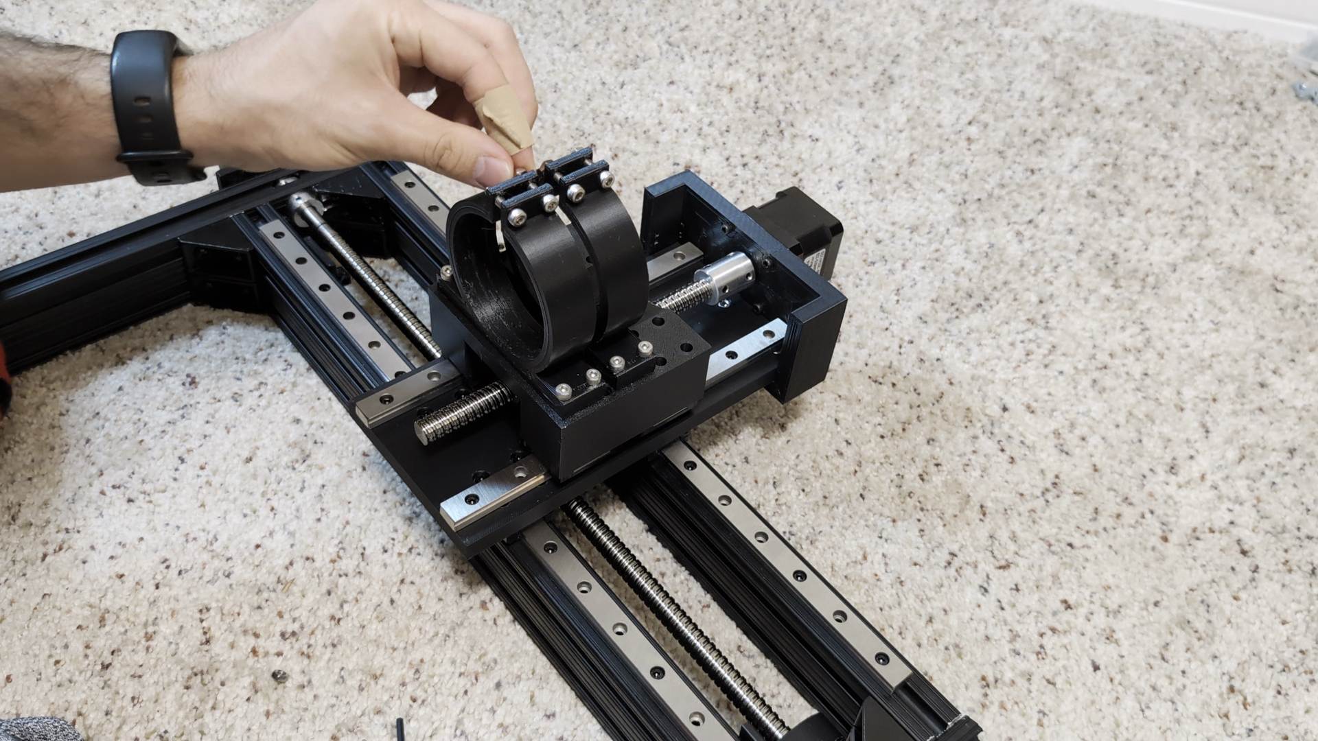
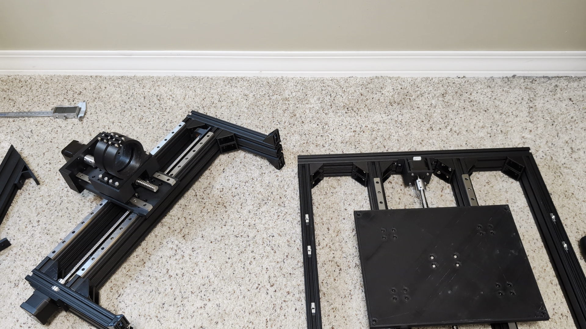
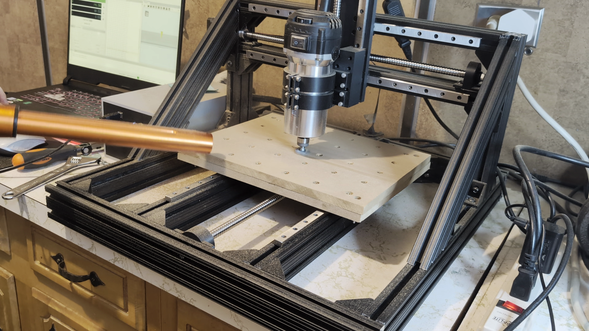
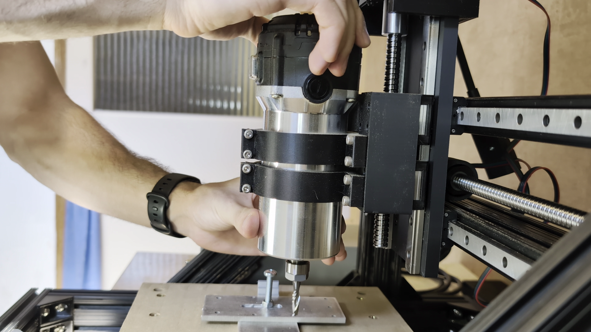
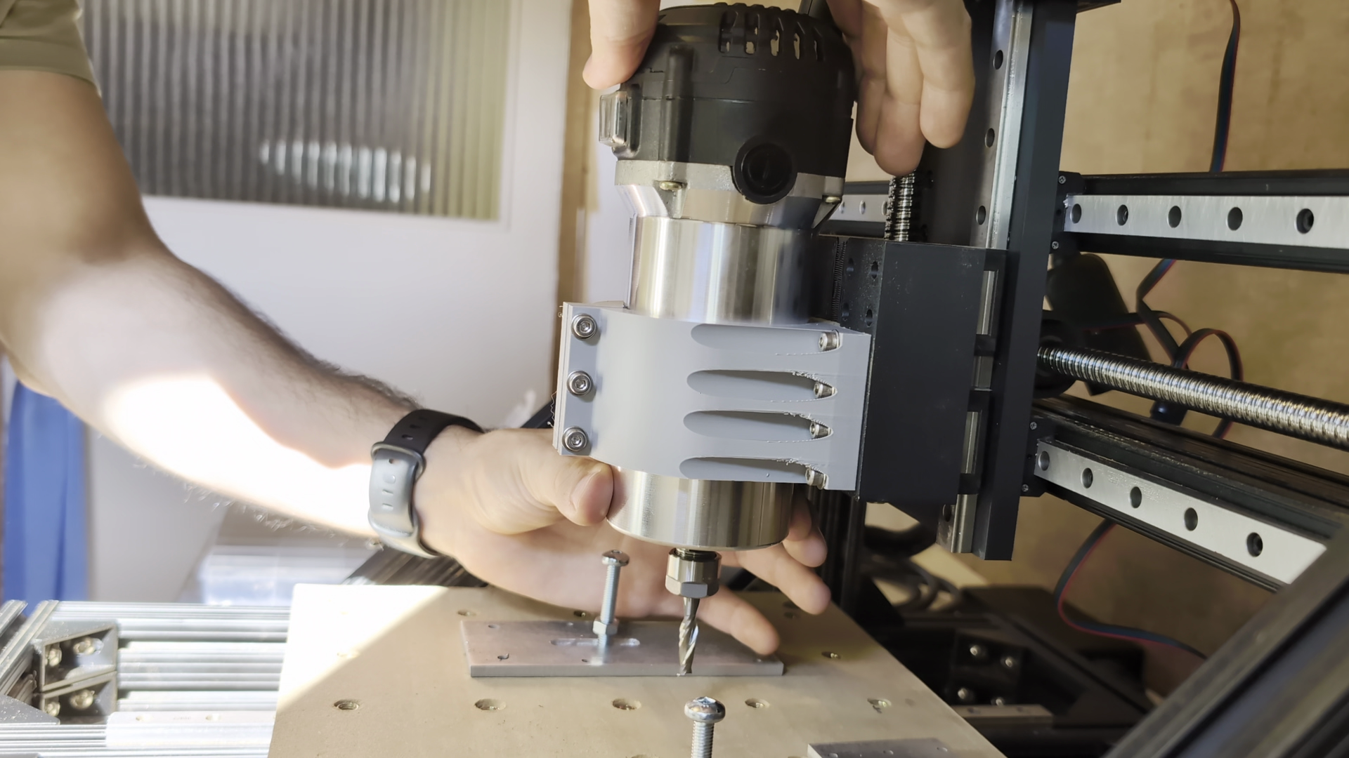
Final Assembly#
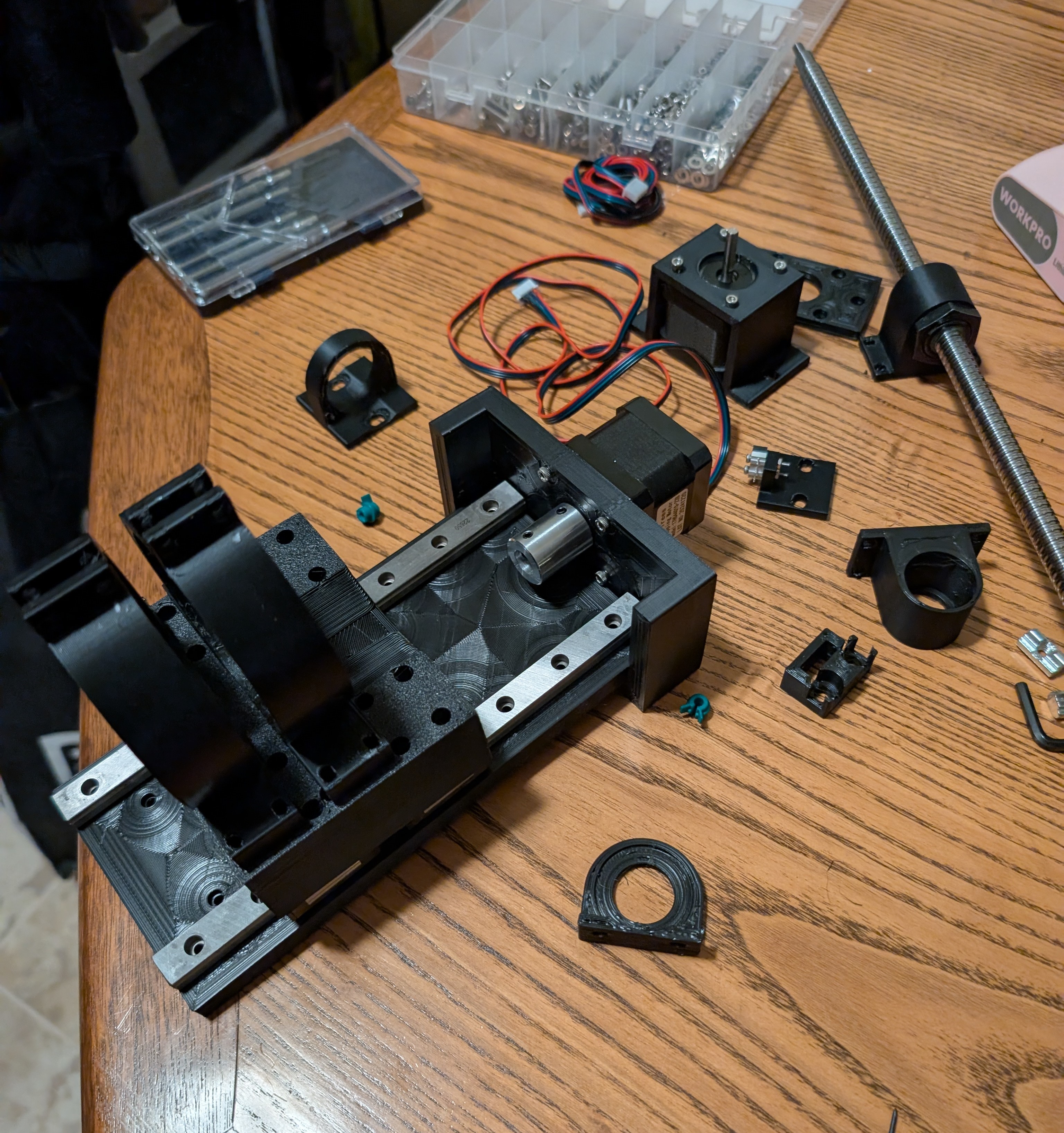
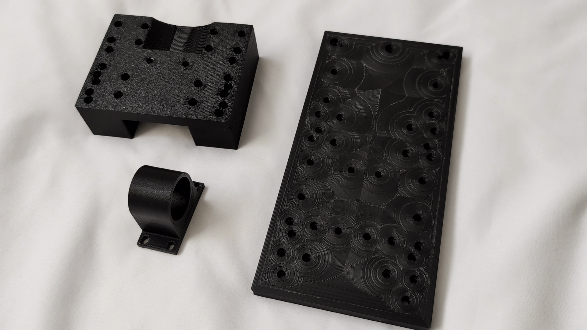
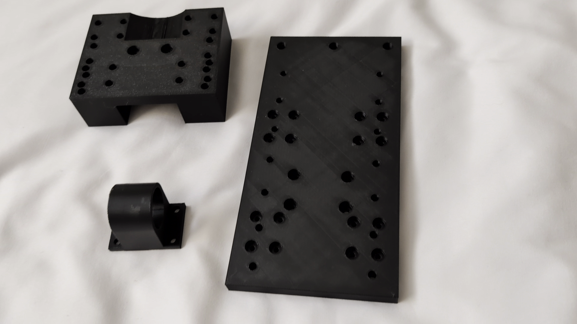
With everything prepared I started the final assembly. Though, as expected, it revealed a few changes that needed to be made. I had to modify the Y axis bearing mount, modify a corner bracket to make room for a ball screw coupler, and had to redesign some Z axis mounting parts due to them interfering when assembling.
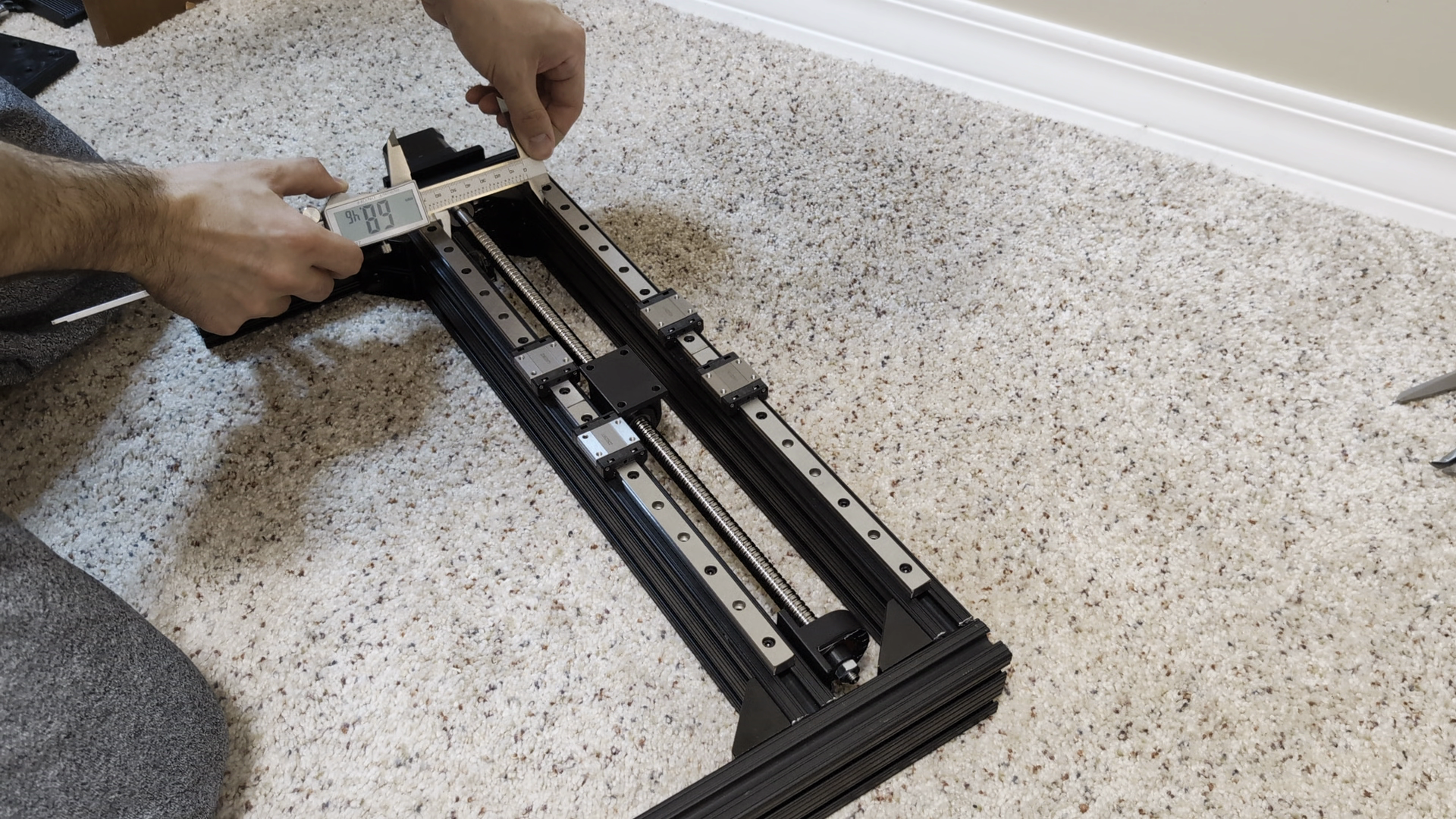
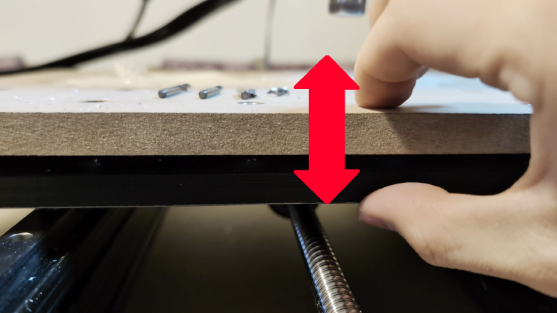
Now it was time to put everything together. Using a straight edge and calipers to ensure all the rails were spaced correctly and parallel and crossing my fingers that I wouldn’t have to immediately take the whole thing apart again, it was pretty satisfying seeing it actually come together according to plan.
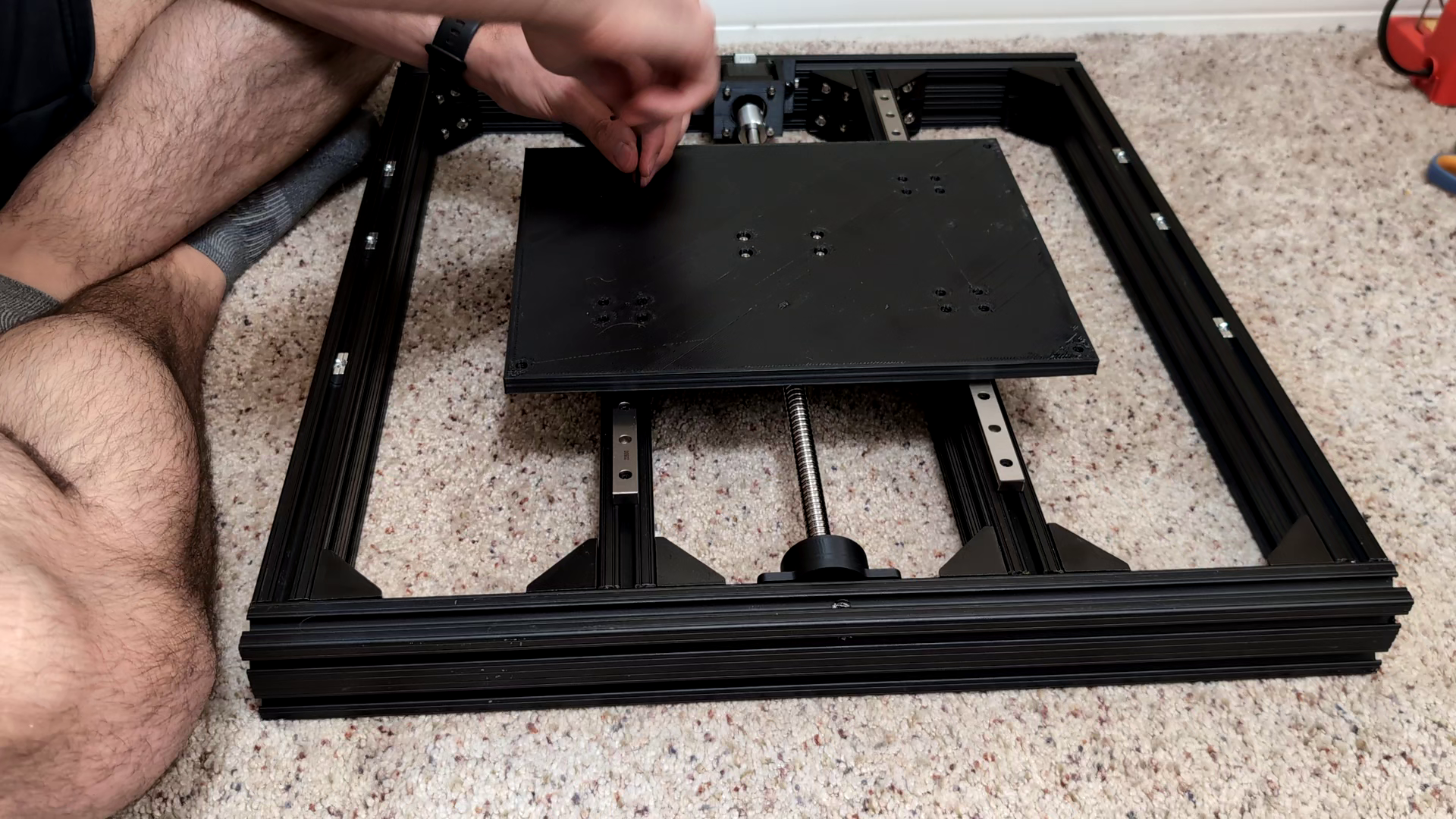
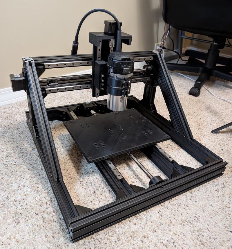
To my surprise As expected, it even moved smoothly on the first go.
Although the router was now basically assembled, it was far from finished. It still needed a real spoilboard with workholding anchors and an enclosure for the electronics, but at this stage it was ready for testing.
Continued Development and Testing#
First Cuts#
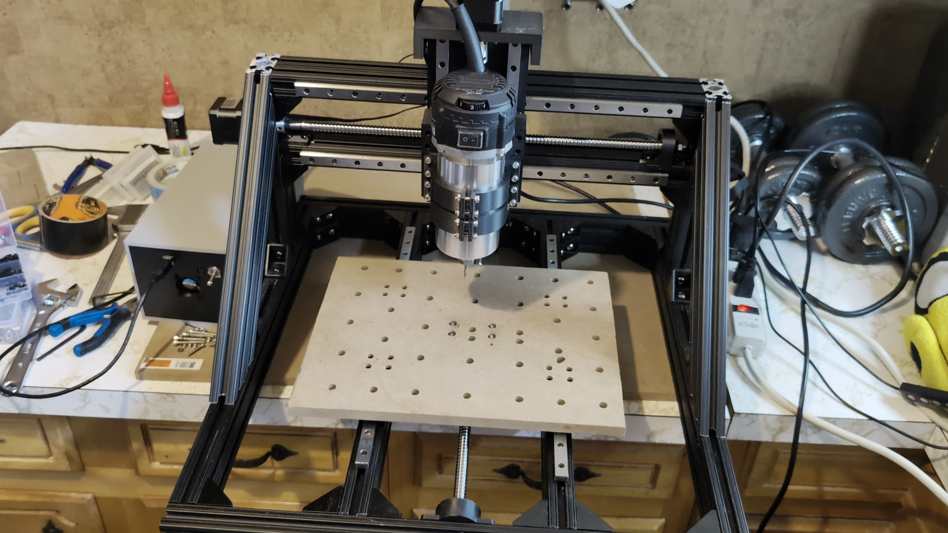
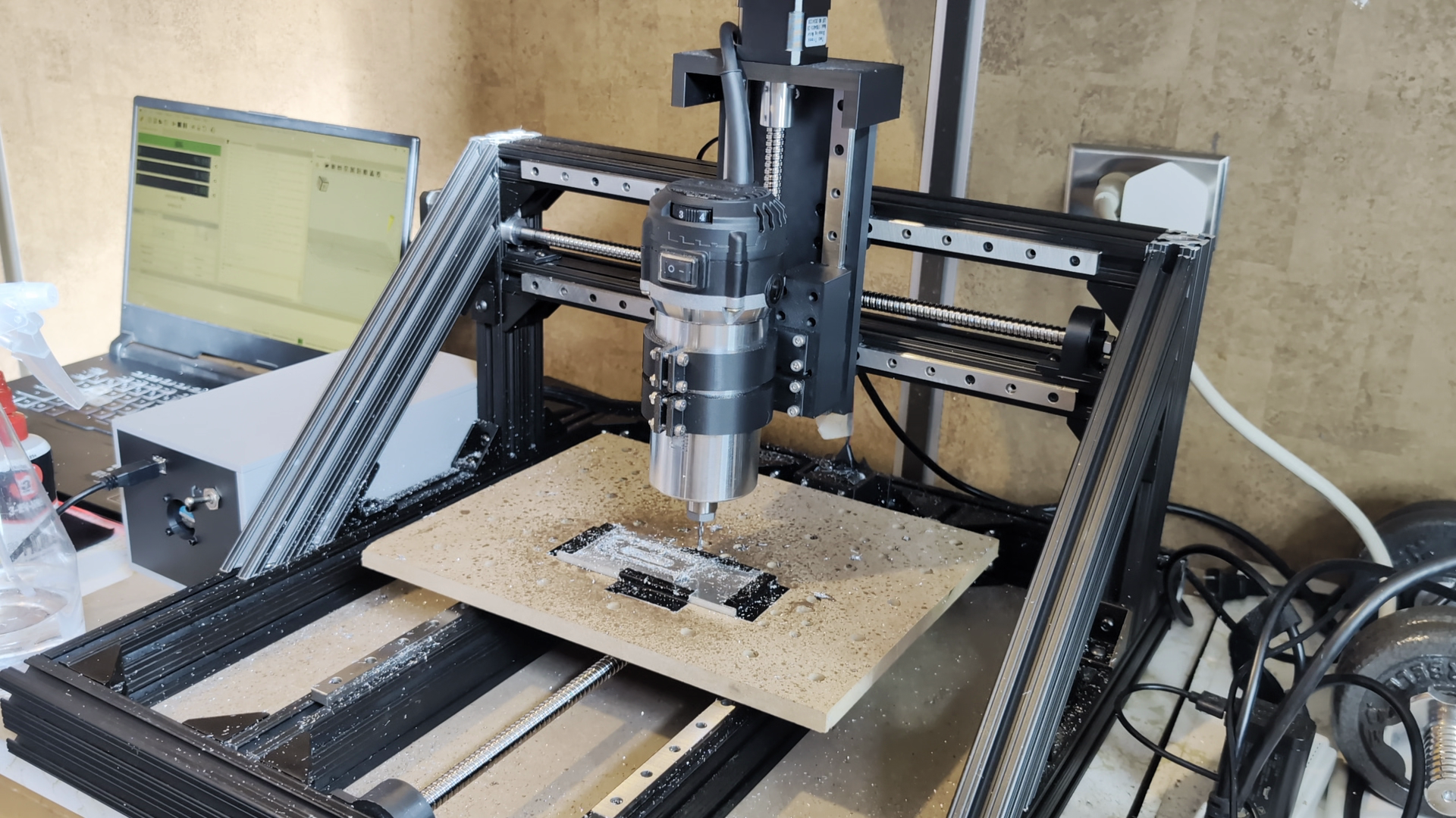
With the machine fully assembled, it was time for a “hello world” first cut. For this cut I used a makeshift spoilboard made of some thin plywood, and duct taped the stock material to it.
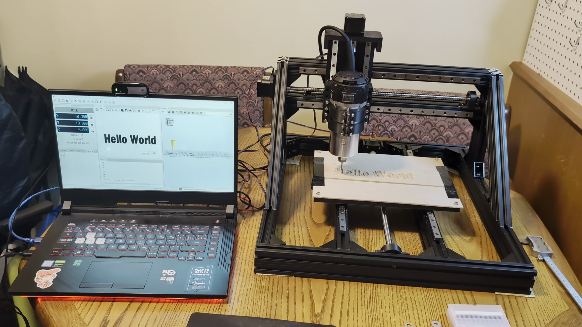
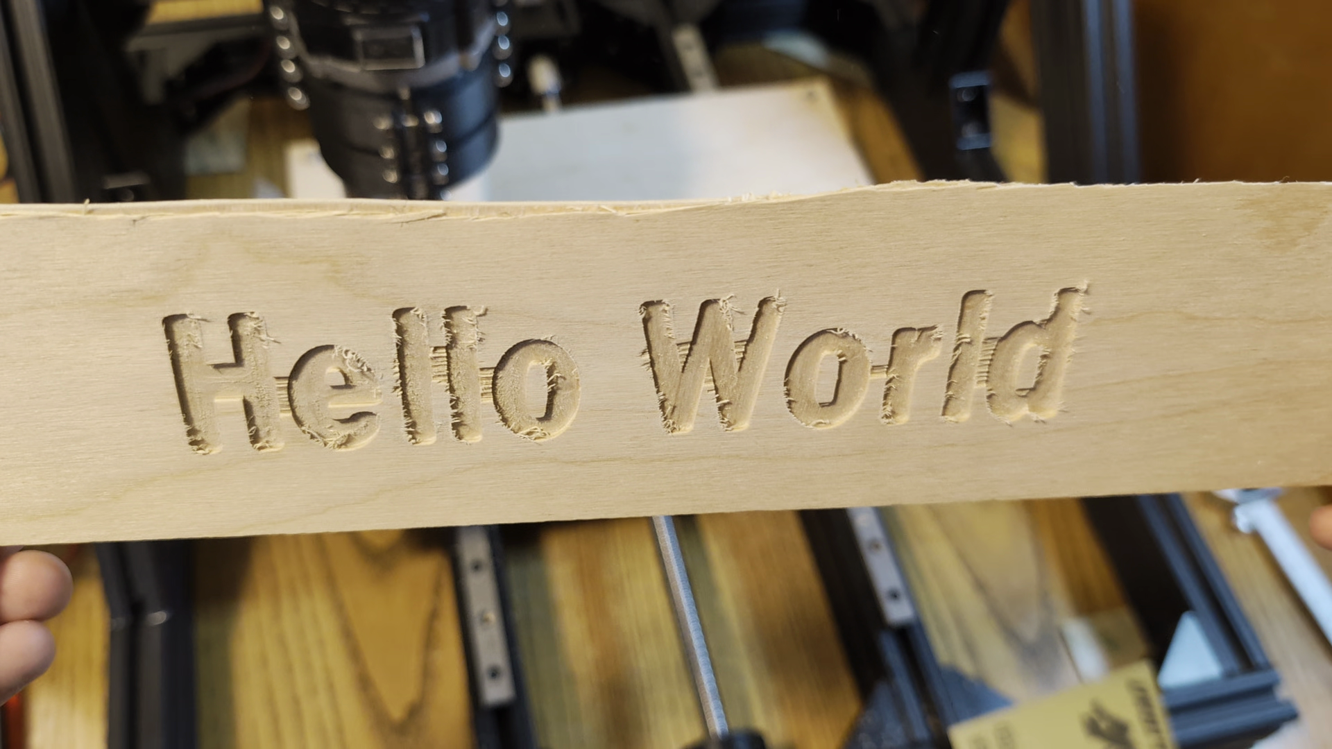
Despite some chattering and chipping the first cut came out pretty good. It was a great feeling finally seeing the results of all the effort it took to get to this point, but now it was time for a harder test - aluminum.
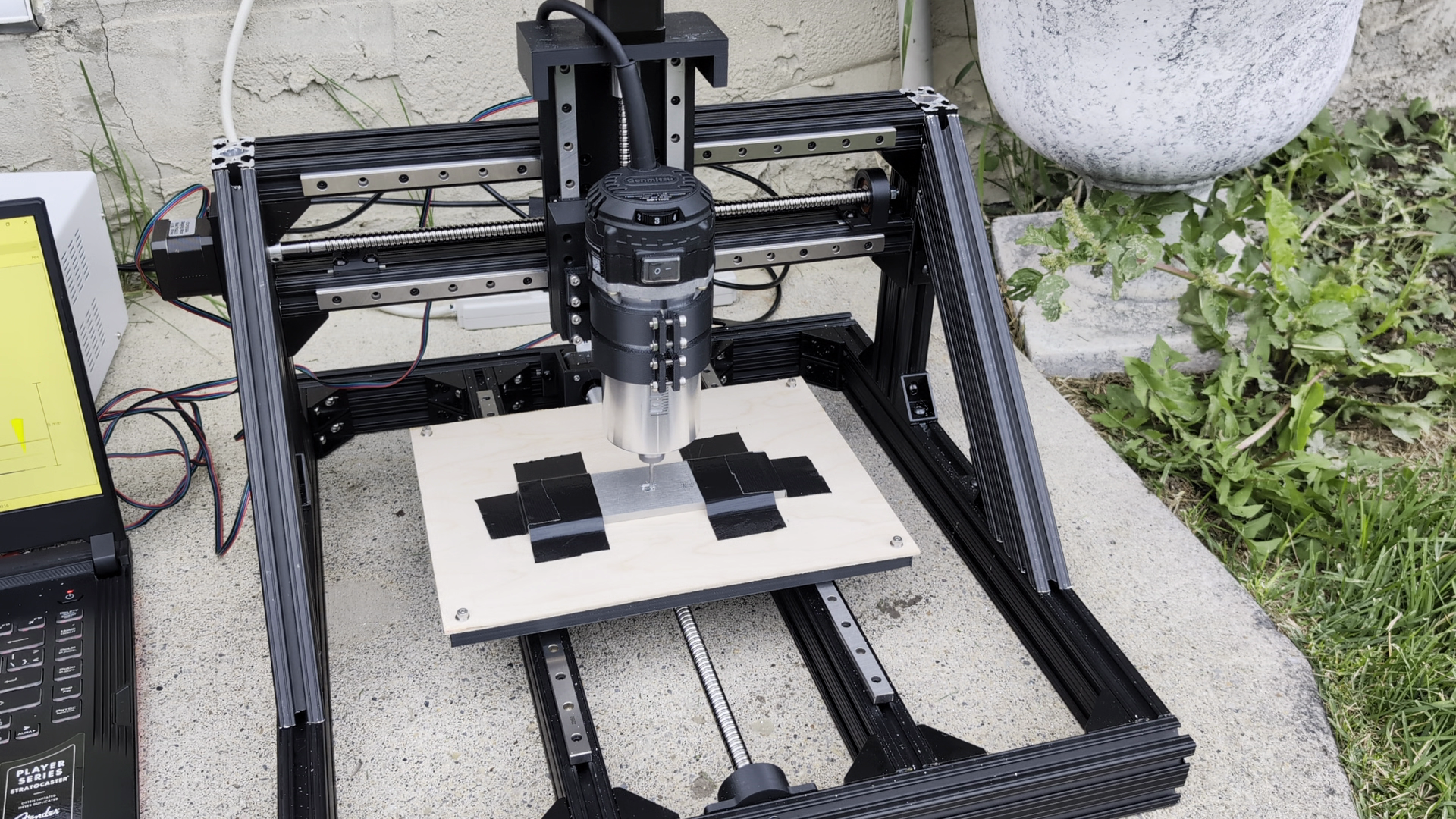
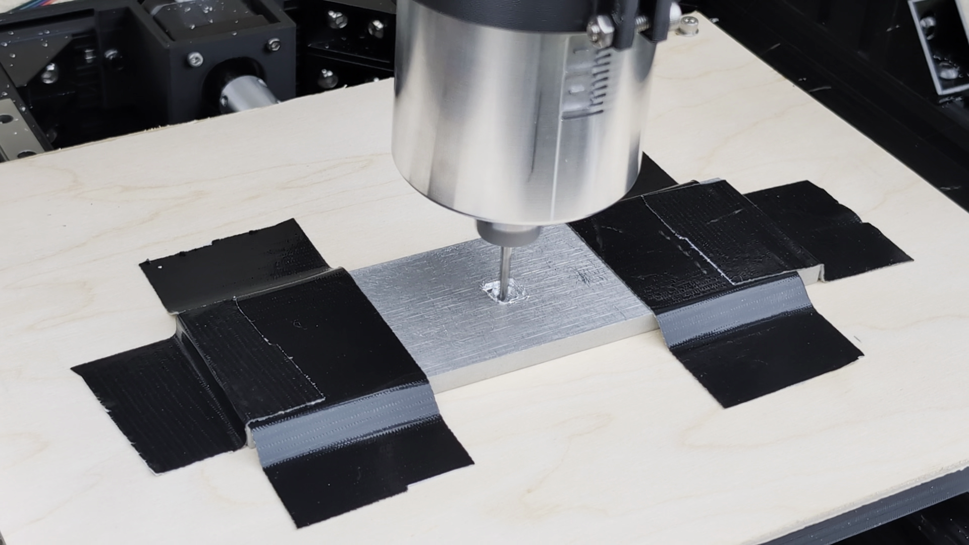
This cut was quite loud and chattery with lots of vibration, but it actually did cut a mostly square pocket without breaking which I was impressed by.
Very satisfied with the initial testing, the next step was making a better spoilboard.
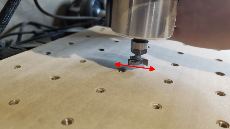
Spoilboard#
For the spoilboard and workholding I bought a board of 1/2" thick MDF along with some threaded inserts.
After fastening the spoilboard down to the bed, it was time for another test. This time did not go so smoothly…
Ball Screwed#
The Z axis ball screw was getting jammed, but only when moving down. I noticed this when I was first assembling the ball screw and it seemed to get better when working it back and forth, but clearly screwing it a few times and praying did not do the trick. After some research I theorized that some balls must have gotten past the return on the top side of the nut - probably after some attempted maintenance in the past and likely the reason I found it in the scrap bin. This means that instead of the balls recirculating back to the groove and rolling between the screw and nut, some were just rubbing up against the seal on the top part of the nut.
So I had to screw the nut off, but if you’ve ever had to take a ball nut off the screw for the first time you’ll know there is nothing more terrifying. The balls are captured between the screw grooves and the nut, so taking the nut off means risking the balls flying everywhere and beginning a very tedious re-assembly process. A cylinder the same size as the ball screw would have helped here, but I needed to access the balls anyways.
Although I couldn’t get every ball back in the track they started in, removing the few balls that were indeed jammed past the top ball return fixed the issue. Is this ball screw going to live forever? Probably not. Does it actually work now? Yessir.
It wasn’t time to get too excited though, as I was re-assembling the Z axis I noticed something else that didn’t look quite right…
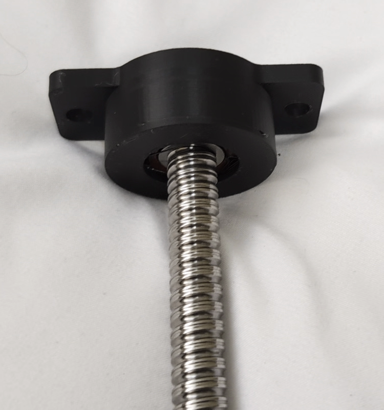
Coupler Wobble#
The coupler between the motor shaft and ball screw was clearly not aligned for both X and Y axes, despite my efforts to shim them to size during assembly.
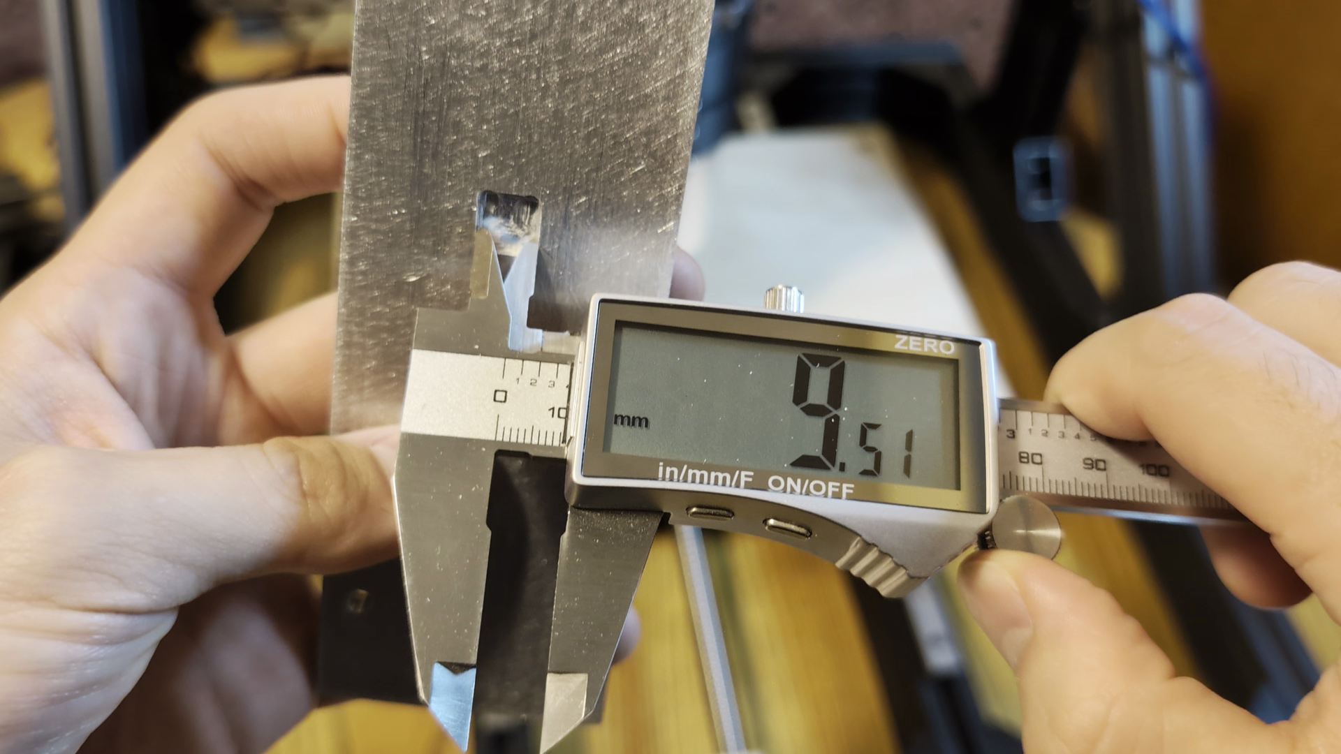
What happened was on top of cheaping out on solid couplers instead of flexible ones, I also mis-sized them. I measured the diameter of the shaft end to be 10mm and assumed both sides were the same, but turns out the side I planned to couple to was actually 9.5mm. Nothing some business card and heat shrink shims can’t fix.
Torquing Out#
Though the Z axis was moving well and the screw wobble gone, the problems were not. This was meant to be a yin-yang symbol, but the cut was slow and glitchy. It seemed like it was struggling and dragging the toolhead through mud as it cut.
The steppers were skipping steps (the rotor slips out of sync with the stator orientation resulting in no movement at all) as soon as you turned the speed up past ~2500mm/min as you can hear in this clip.
This was happening for both the X and Y axes even though the carriages moved smoothly when disconnected from the ball nuts, the ball nuts themselves spun without resistance, and my earlier calculations suggested that there should have been lots of torque to spare. I ensured the current limit was set to the maximum on the driver, and tried lowering the microstep counts, all to no avail.
After some banging my head against a wall, I found that the TMC2208 motor drivers I was using were by default in a mode (stealthchop) that reduced noise but had reduced torque in practice especially at higher speeds. I also had some cheaper simpler A4988 drivers on hand but had assumed that the more expensive ones would be better in every way.
I was incorrect, as after setting up and switching to the A4988 drivers, the machine worked at much faster speeds despite the motors being noisier (this doesn’t matter at all compared to the sound of a router cutting.)
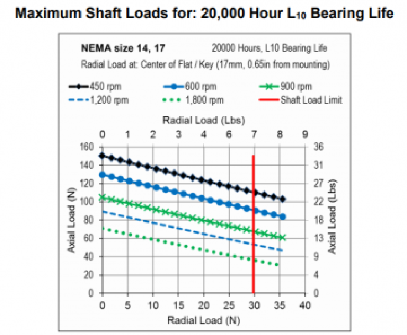
In retrospect I realized that I was cutting it way closer to my initial limits than I thought with these motors. Using the following curve we find that the pull out torque at \(\dfrac{2000\textrm{mm/min}}{4\text{mm}}=500\text{rpm}\) is around 1100gcm.
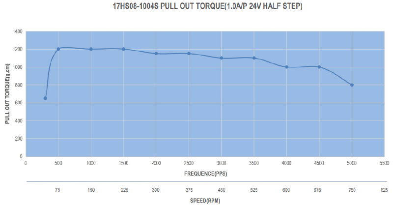
This converts to around 10.79Ncm or 0.108Nm which when plugged into our earlier calculation comes to:
$$F = \frac{2\pi \times 0.108\,\text{Nm} \times 0.70}{0.004\,\text{m}} = 118.75\,\text{N}$$Which is right at the upper end of the 40N-120N cutting forces I was expecting. This leaves basically no room for error especially at even higher speeds like the 2500mm/min that it was stalling out at with no load. At least the A4988 was able to produce closer to this ideal torque. The TMC2208 could produce more in a different mode, but changing it is a somewhat involved process (more on this later.)
With this issue resolved I finished off the spoilboard with some threaded inserts and moved on to the next step.
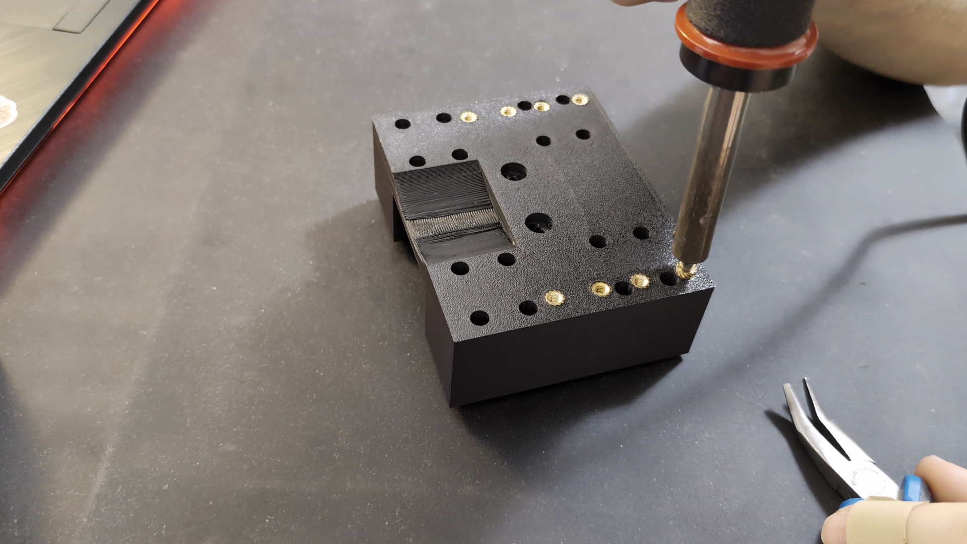
Electronics Enclosure#
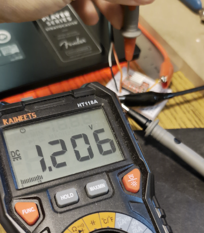
Up until this point I had just been using the exposed arduino powered by a bench top power supply. It was time to set up a permanent solution to power, cool, and protect the components. To this end I planned and modeled the enclosure as shown earlier in the design section. After some printing, soldering, and wiring, there were still a couple hiccups; the internet arduino CAD model I got didn’t match up perfectly with my cheap clone and I had to rip the power jack off. It also didn’t start up properly until I tried to measure the buck converter voltage with a multimeter and it sparked, but then it worked ever since. Electroshock therapy I guess.
First Real Test#
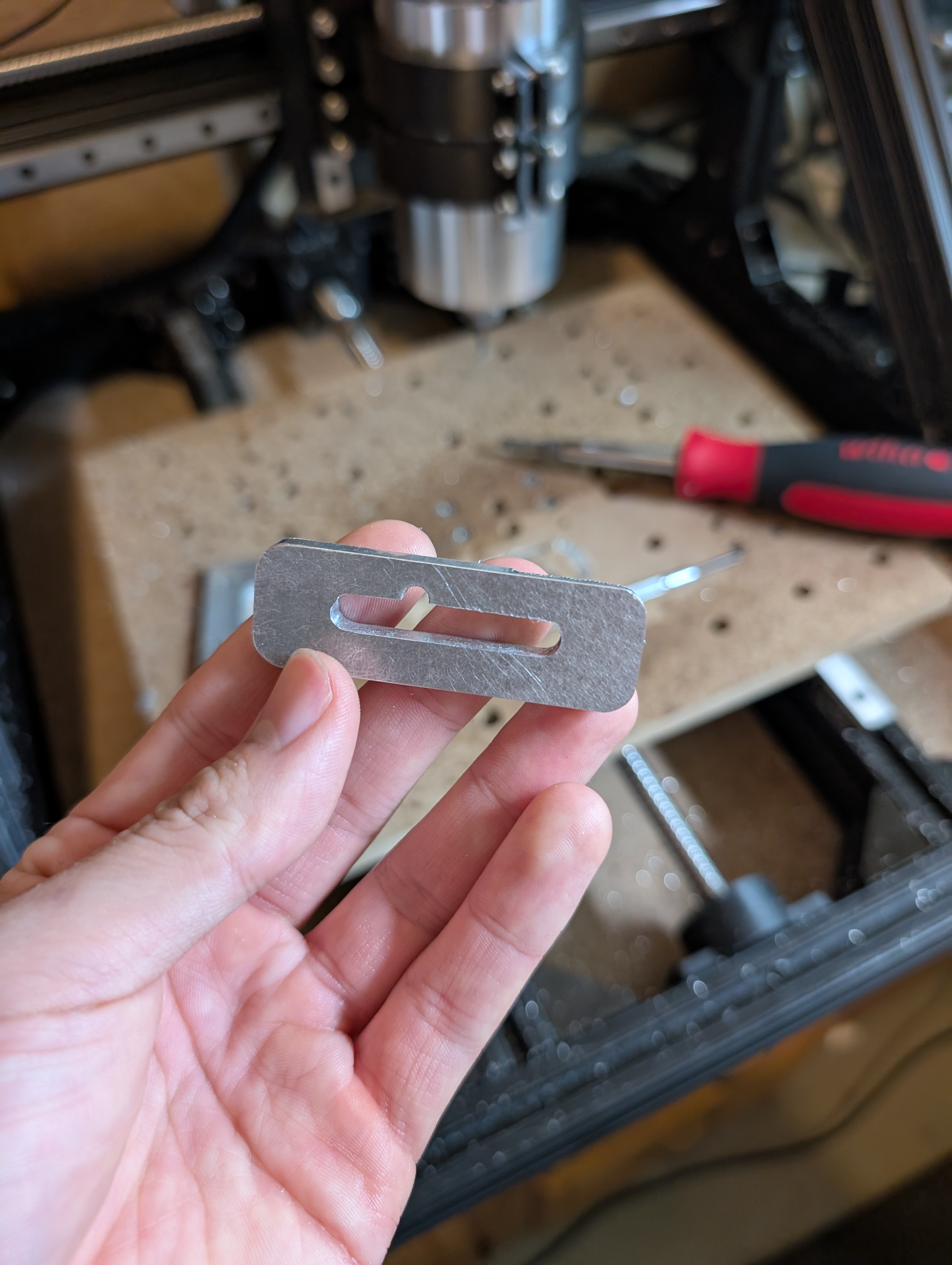
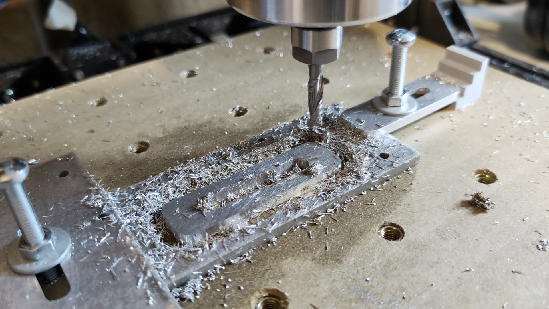
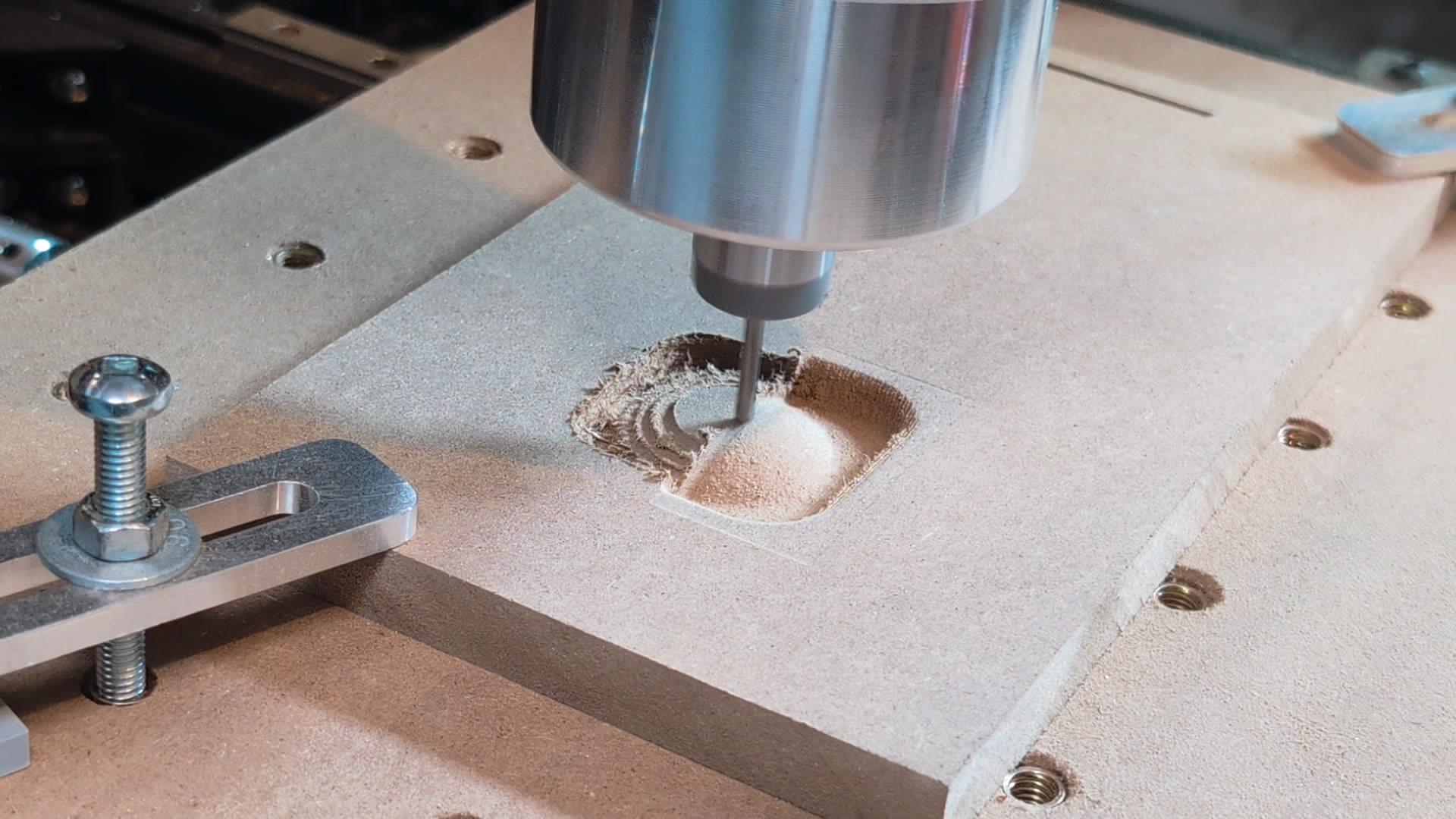
With the enclosure and wiring now in a more permanent and portable state, it was time to try making a real functional part: a small aluminum clamp for work holding.
This is where a few things came together to result in me being glad I bought the cheapest endmill set I could find.
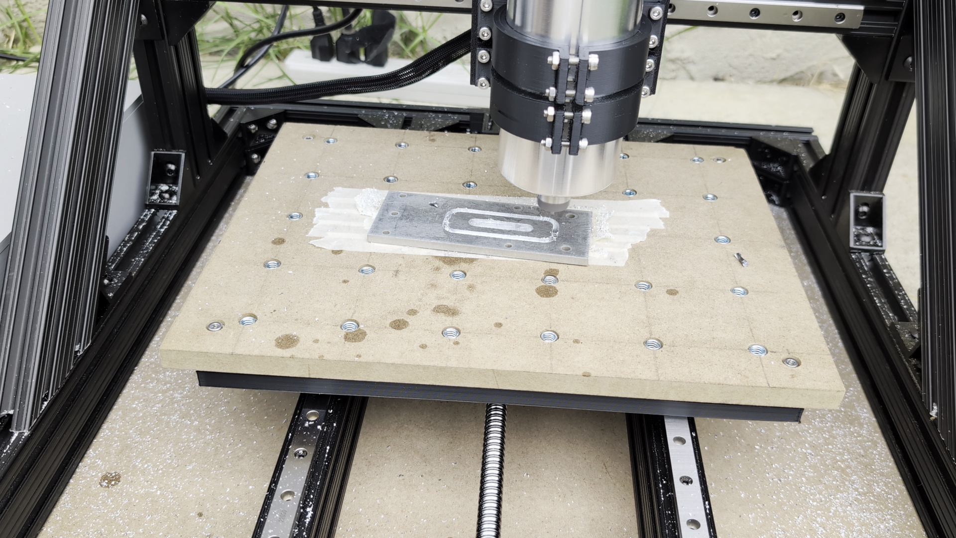
A large factor was my own inexperience in setting up CAM toolpaths, dialing in feeds and speeds, and not using lubricant/coolant for most of the cutting. The cut ultimately failed due to the tape/glue workholding failing, reinforcing my decision to make a clamp as the first order of business.
Aside from this, however, there were also clearly some rigidity issues. Watching the footage the router seemed to flex along the X axis, and the spoilboard (which needed standoffs due to the inserts sticking out,) had a lot of vertical flex to it.
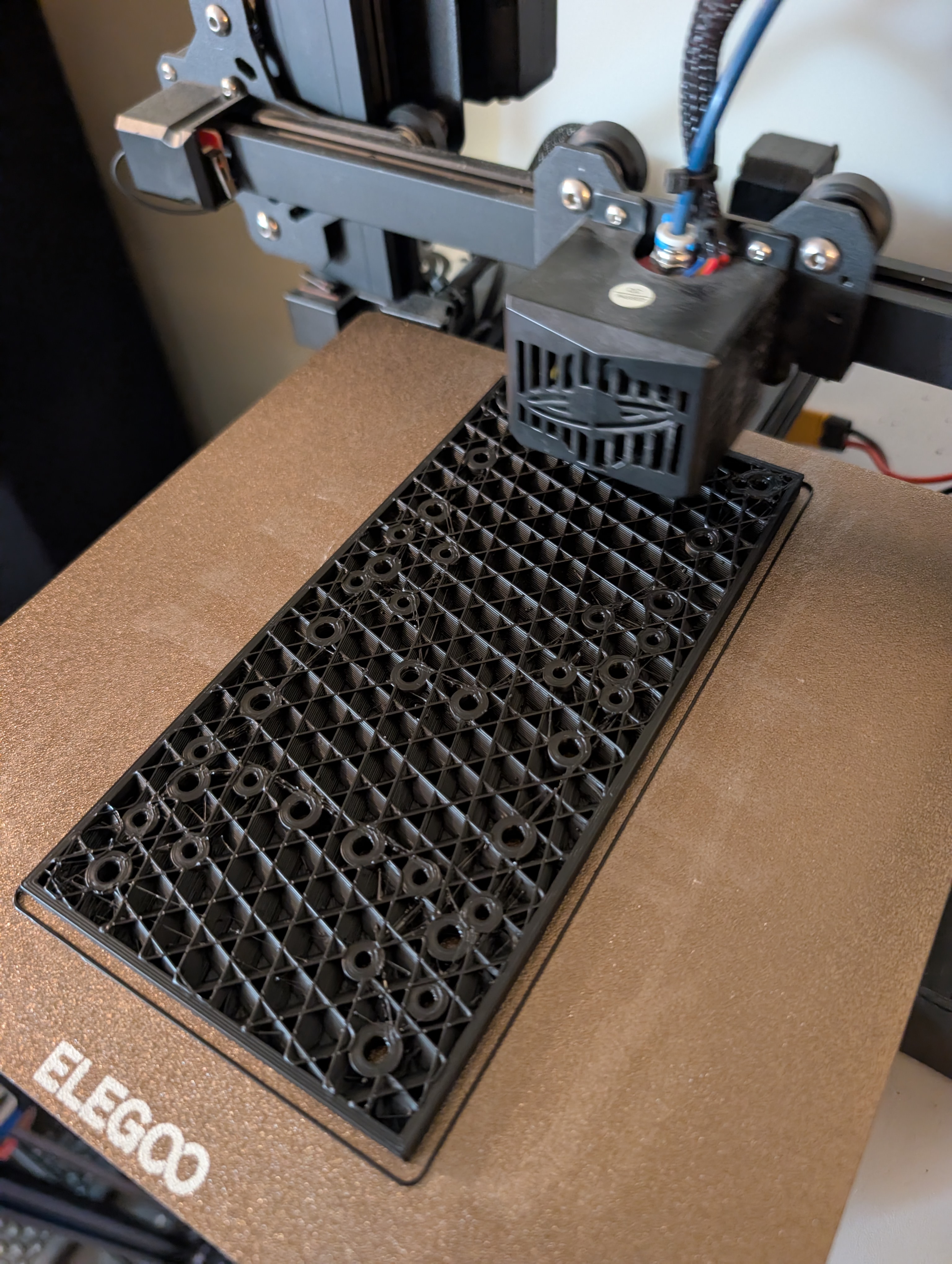
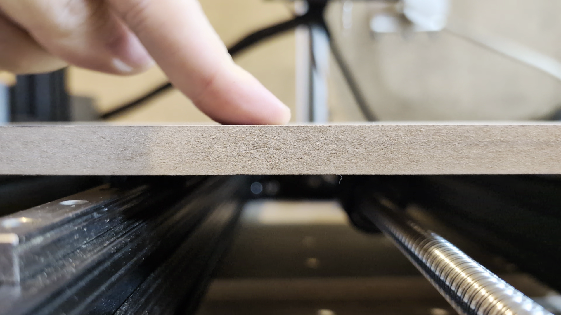
The bed would be the first issue to tackle, by simply replacing the 3D printed bed (which was not meant to be a permanent solution) with a bed made of the 1/4" MDF.
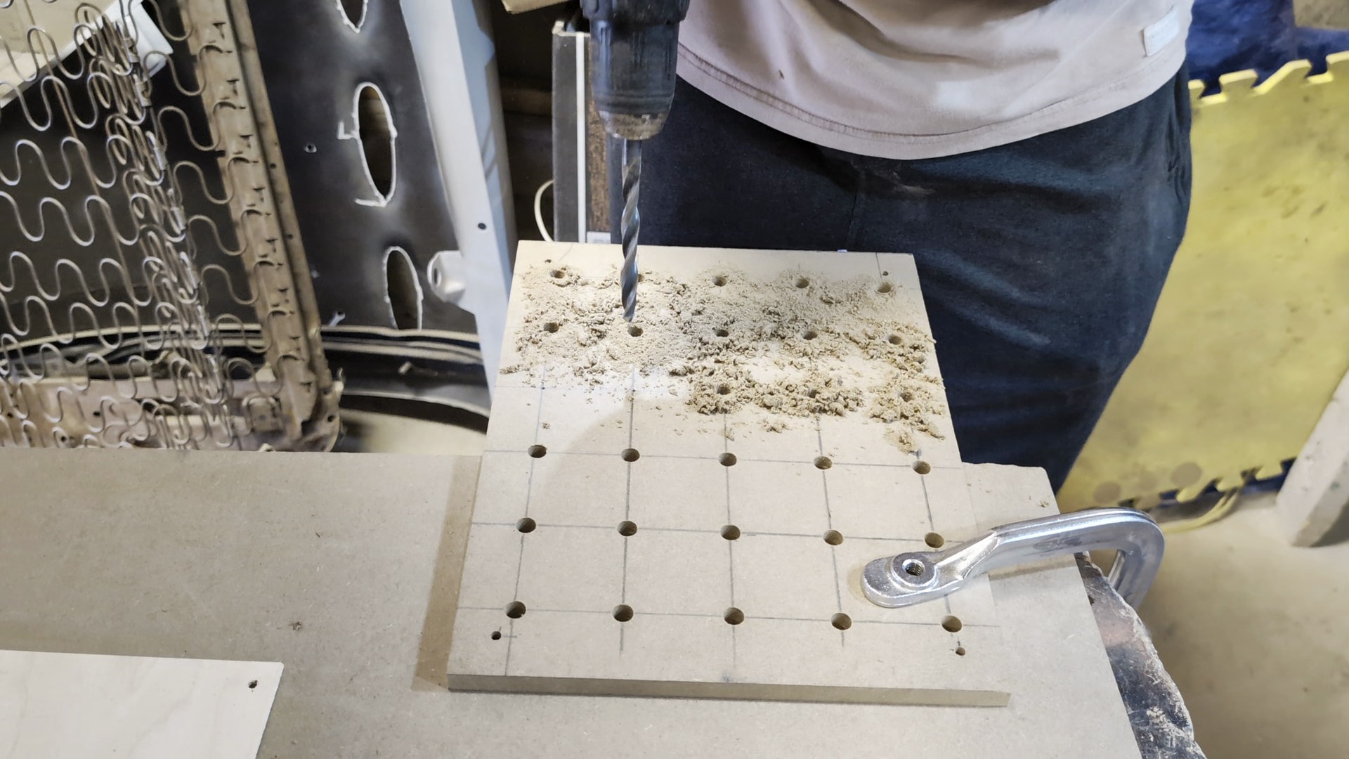
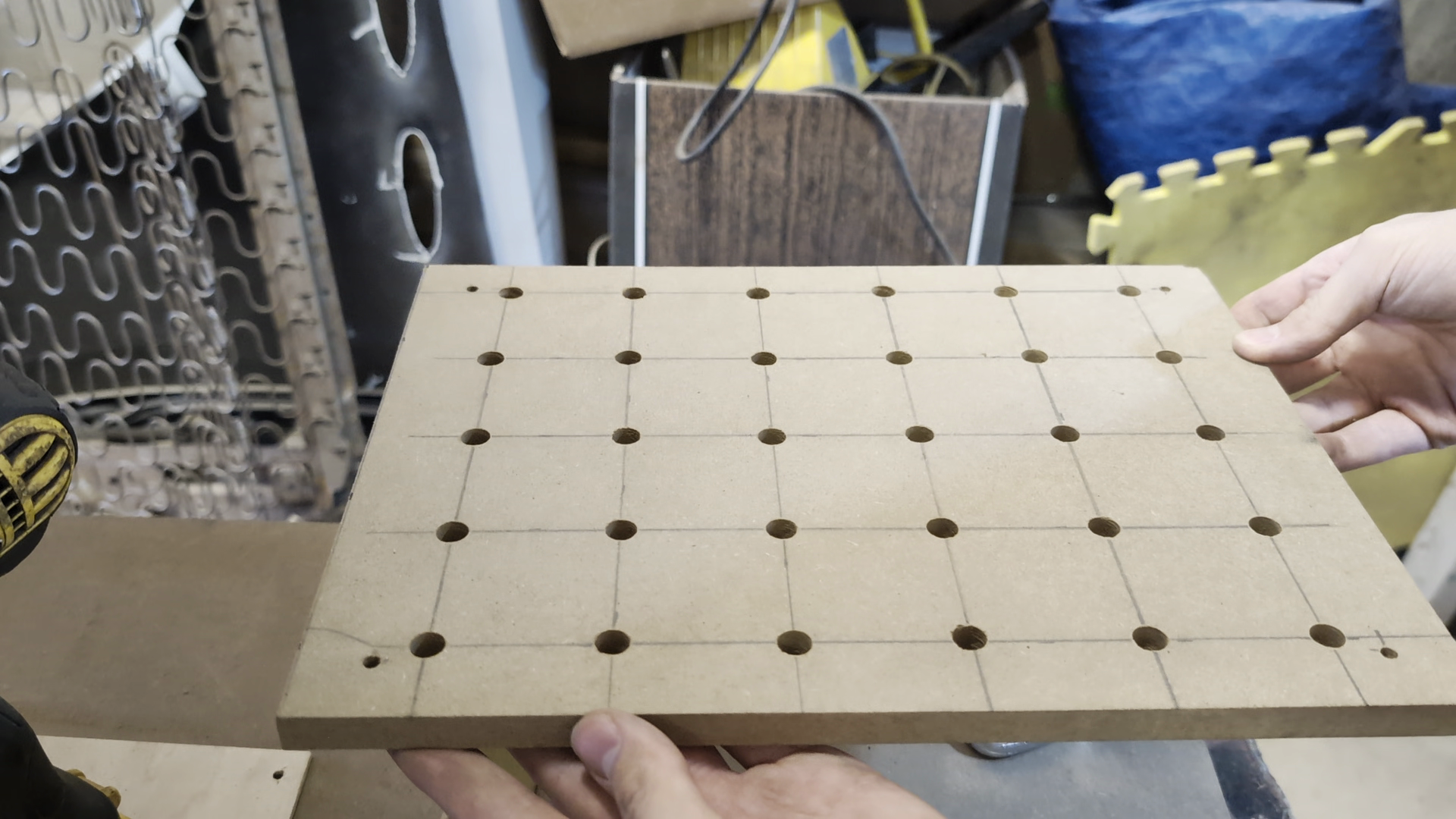
New Bed and New Problems#
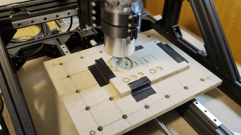
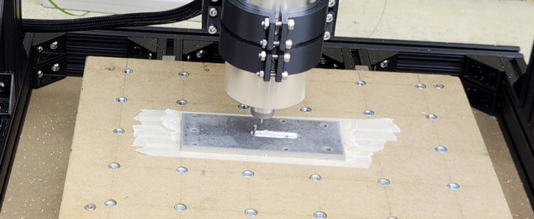
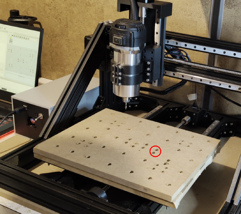
To make the new bed I had to drill a bunch of holes in precise positions; good thing I now had a machine that makes this easy.
I had it cut some holes for mounting to the linear rails, the Y axis coupler, and some large holes for threaded inserts. This went well at first, until I noticed the holes started to not line up with where they were supposed to be, and it started drilling a second hole only millimeters away from the hole it just drilled.
I assumed the drivers may have been overheating as they will stall when this happens. My suspicions seemed confirmed when I reached into the enclosure and nearly burned my finger touching the heatsink, so I ran the rest of the cut in 5 minute increments which gave it time to cool and allowed it to finish.
The MDF was much stiffer than the 3d printed bed, as expected.
Now for some reason here I decided to give another go at cutting the clamp even though I would have to use the bed directly as a spoilboard and the driver issue meant pausing and waiting for it to cool constantly. What could go wrong?
Second Real Test#
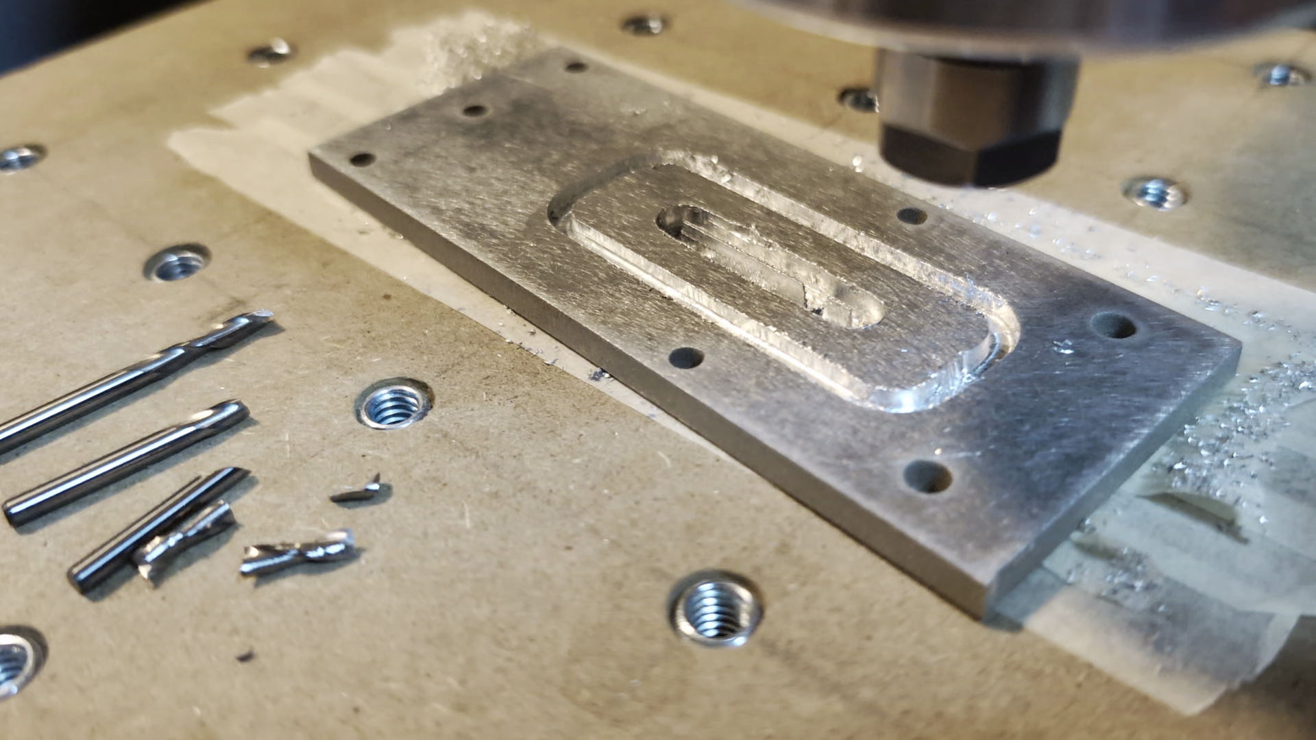
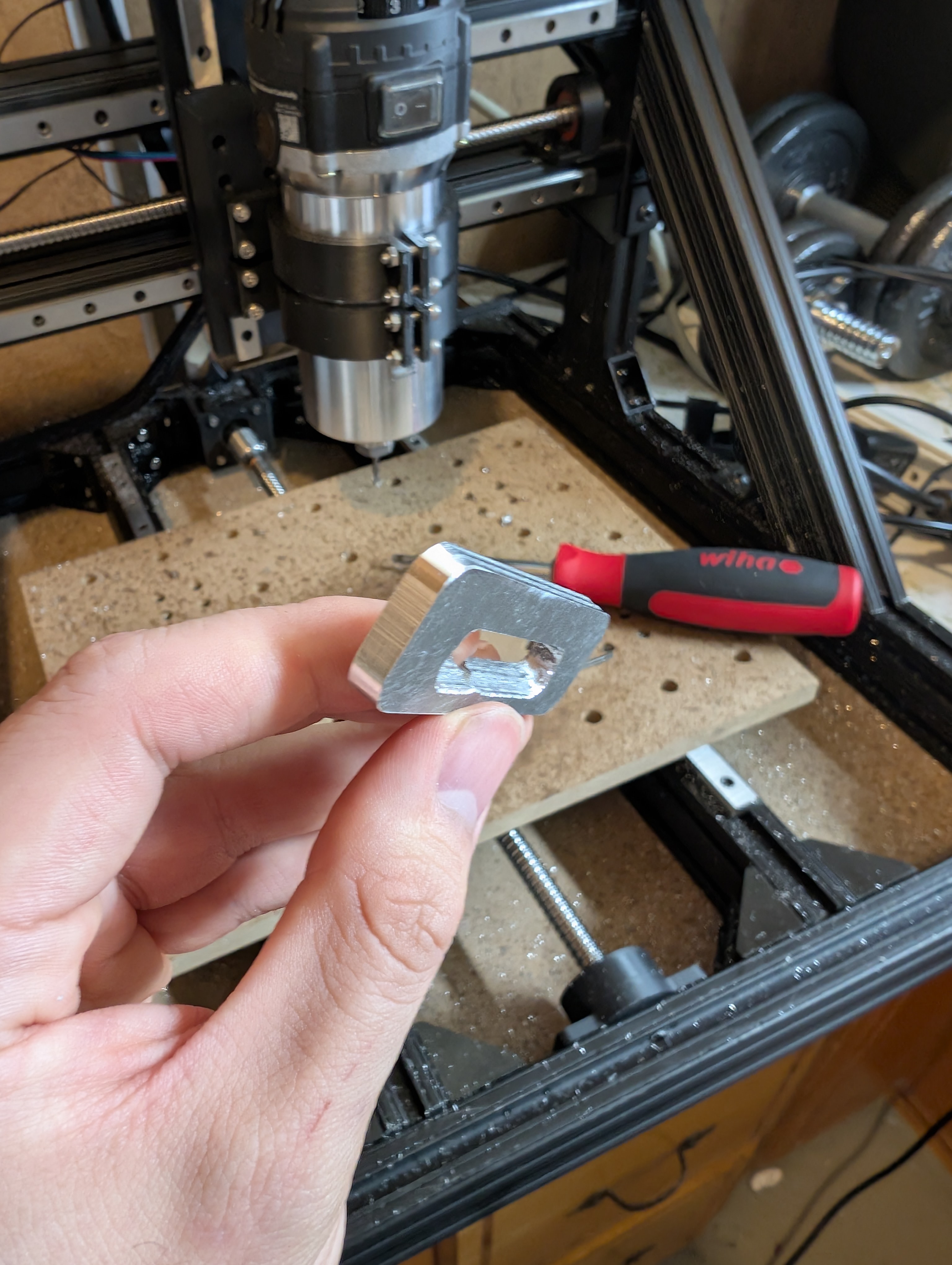
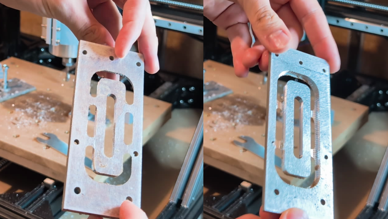
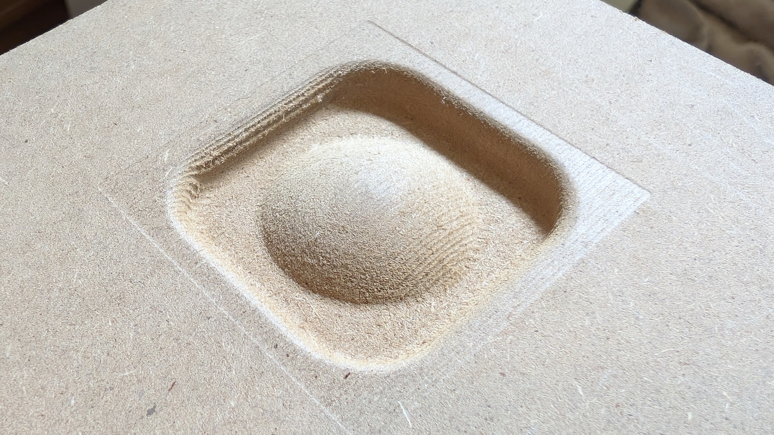
With a stiffer bed and some ideas to try for feeds, speeds, and lubricant, I gave the aluminum clamp another go. This was a good learning opportunity for dialing in feeds and speeds as well as trying out both oil and isopropyl alcohol as lubricants. This time it finally completed with only one endmill down and only some minor defects.
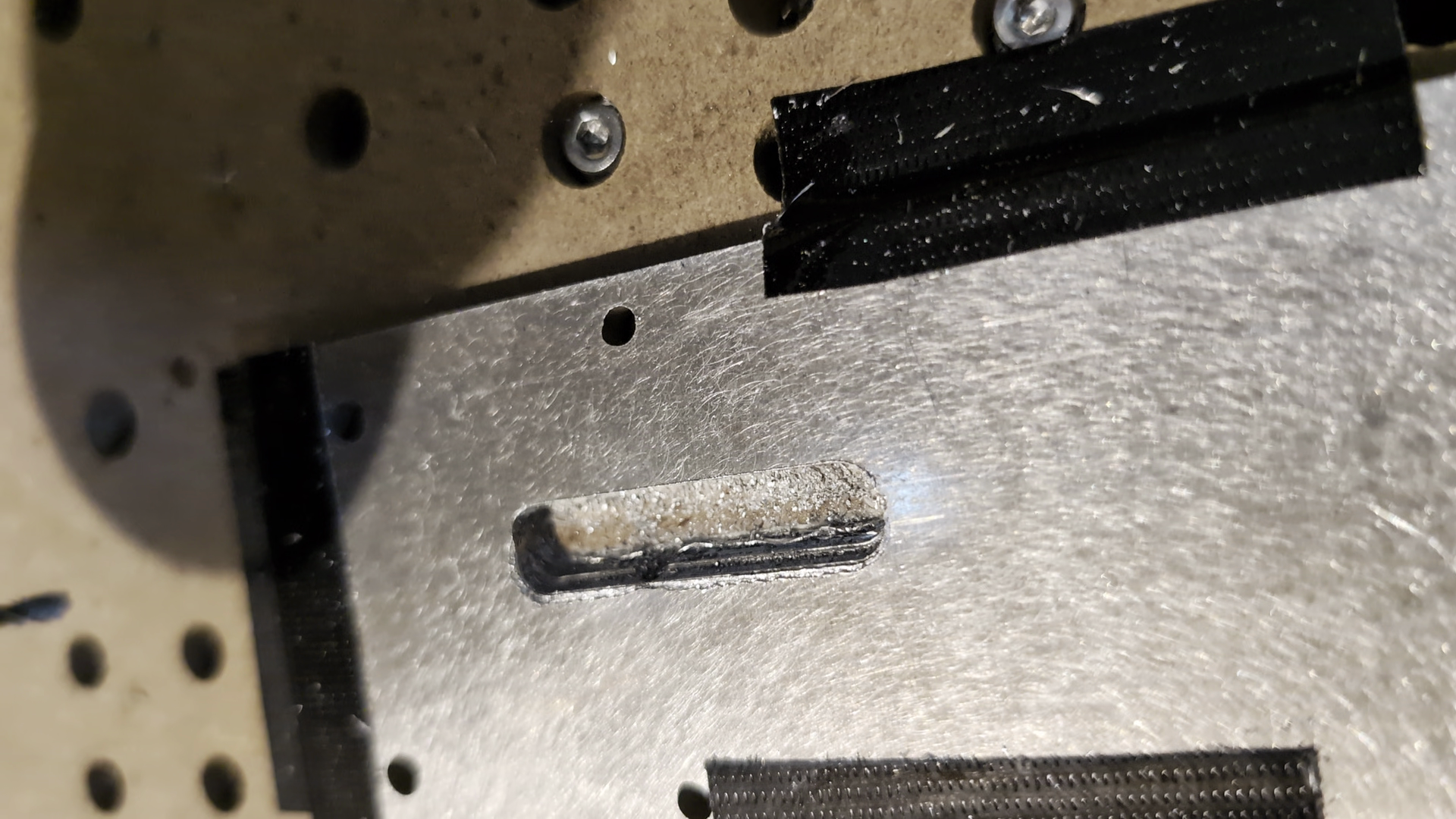
The stair step type look was from me not fully tightening the Y axis coupler and it slowly loosening off over the course of the cut, and the slot was from losing the zero position after one of the pauses to let the drivers cool. These issues aside, I was quite happy with how this turned out.
Spoilboard (again)#
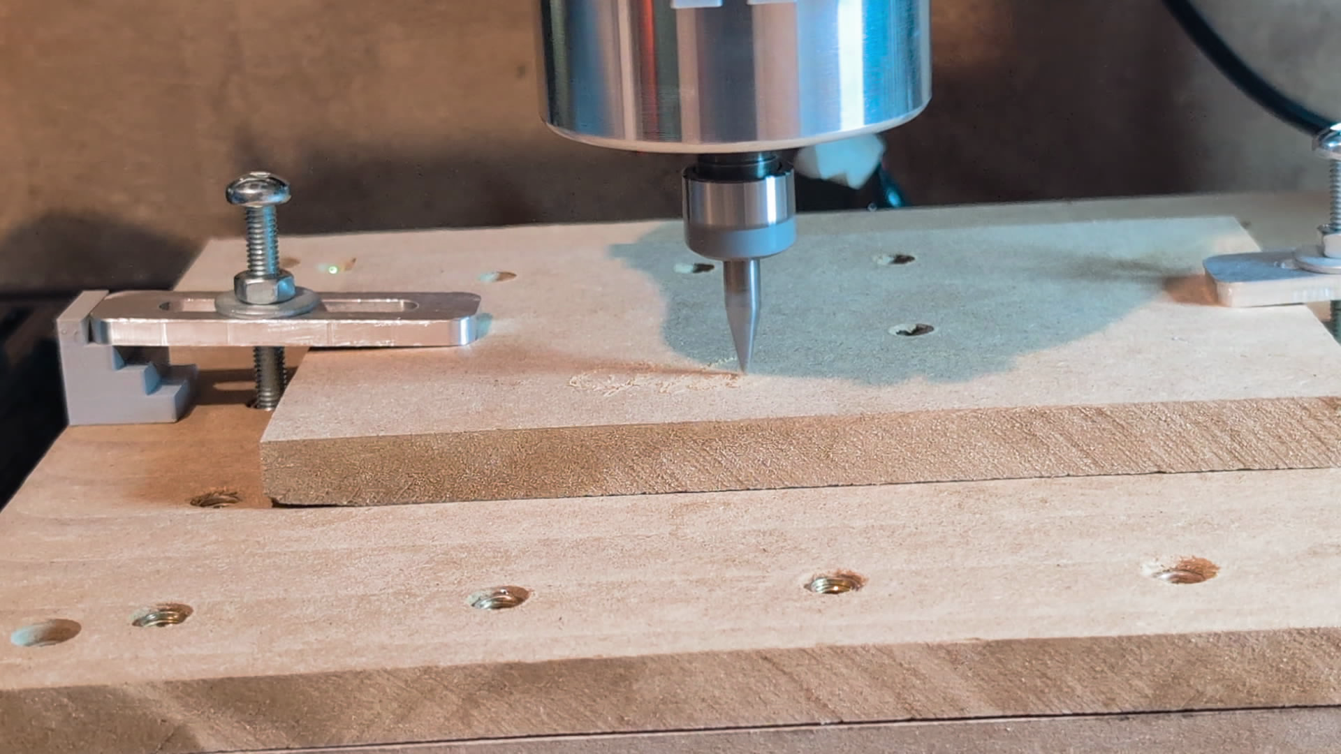
I decided to make another spoilboard to top the MDF bed so the bed itself wouldn’t need to get remade when replacing it. This time after cutting the holes, threading the inserts, and testing the clamps, I surfaced the bed so it would be level relative to the tool. I definitely should have waited to do the inserts until after surfacing, as running the surfacing cut with the threaded inserts only a couple millimeters deep past the surface was pretty nerve wracking. However, after screwing some in further as needed it finished without self destruction.
There was, however, noticeable patterning which seemed due to the router being able to flex in the Y direction.
More Rigid Mounting#
The whole router was able to flex slightly while the carriage stayed rigid, so it was clear that the thin mounts I had made to clamp onto the router were not doing the job.
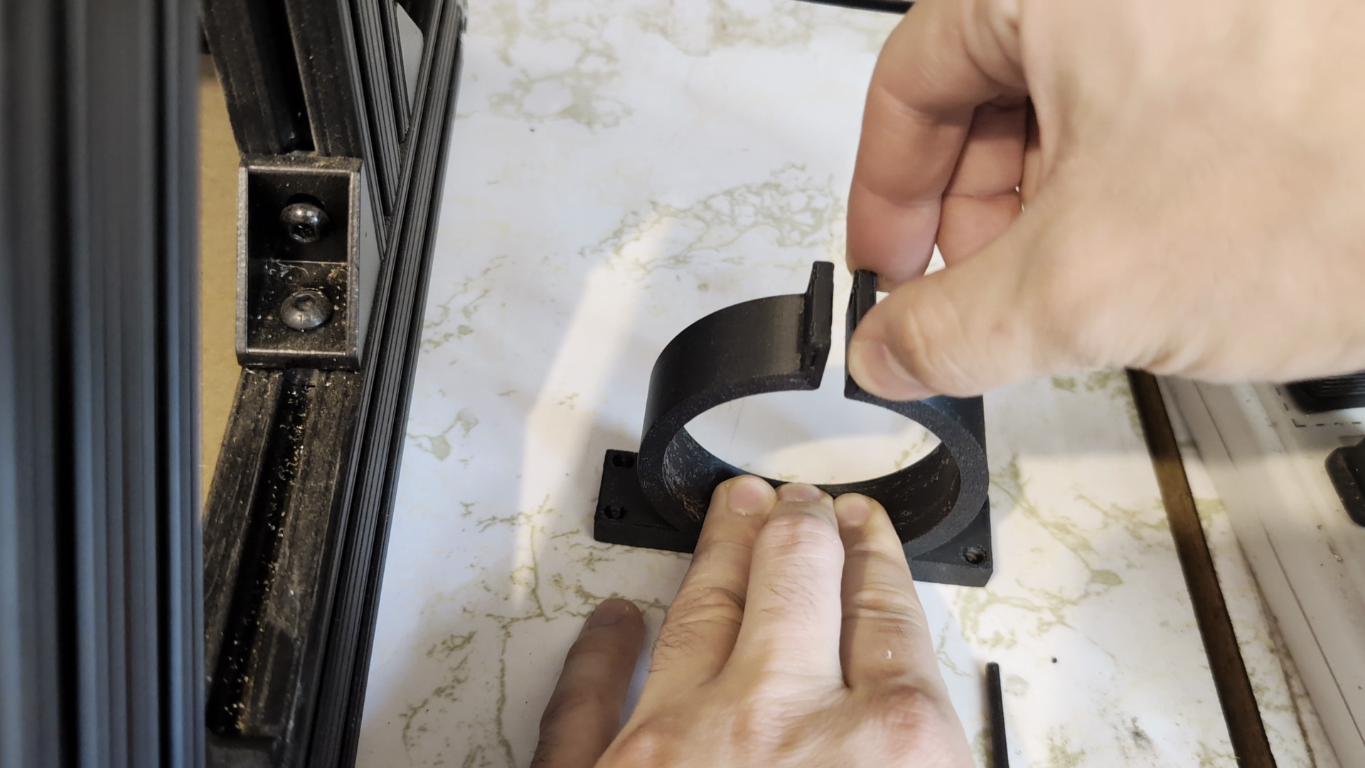
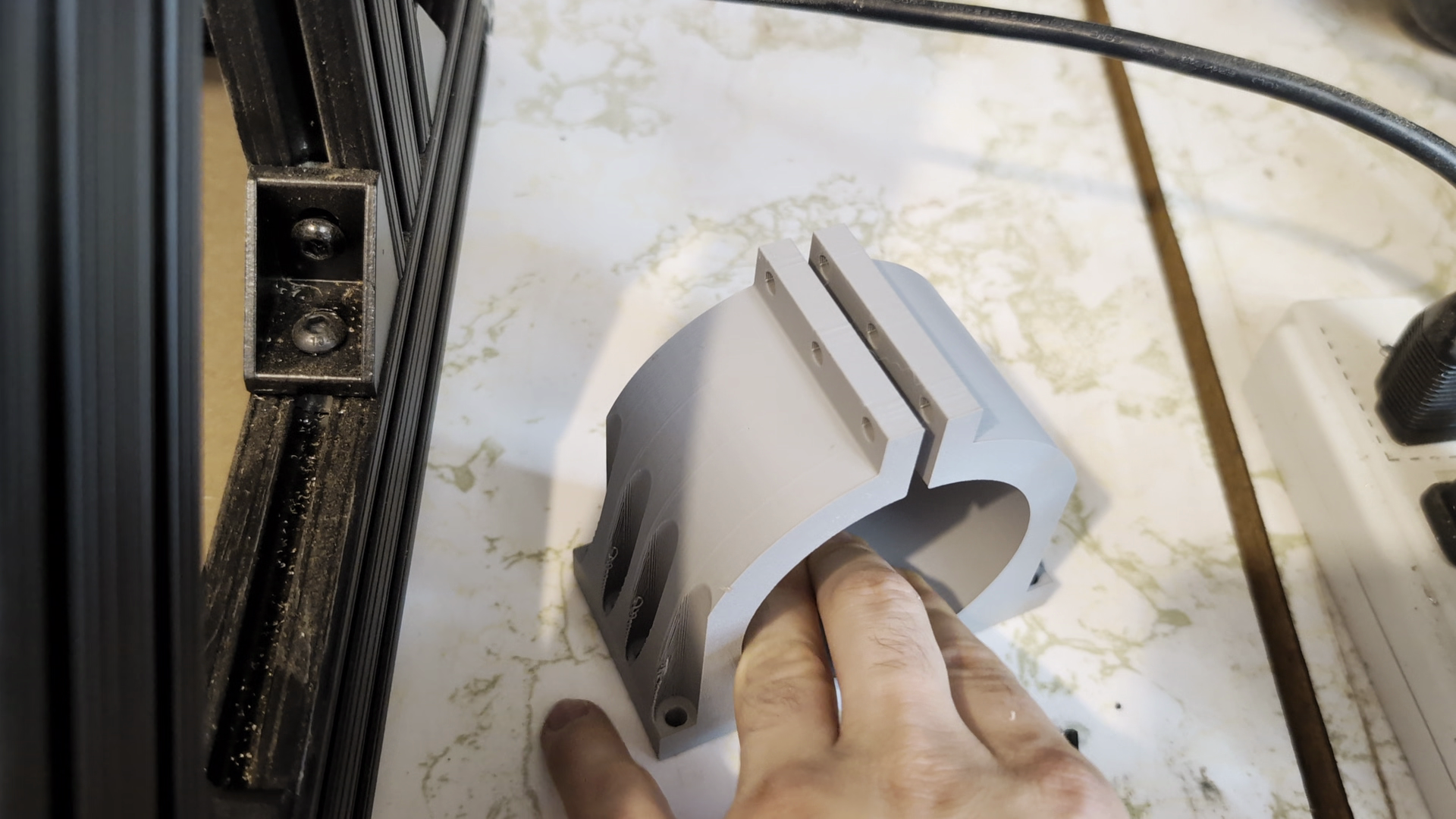
After modeling and printing a much beefier mount the flex was reduced substantially. Now there was just the overheating issue to handle.
Cooling Things Down#
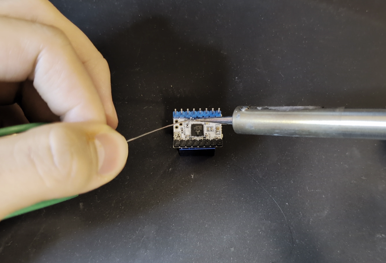
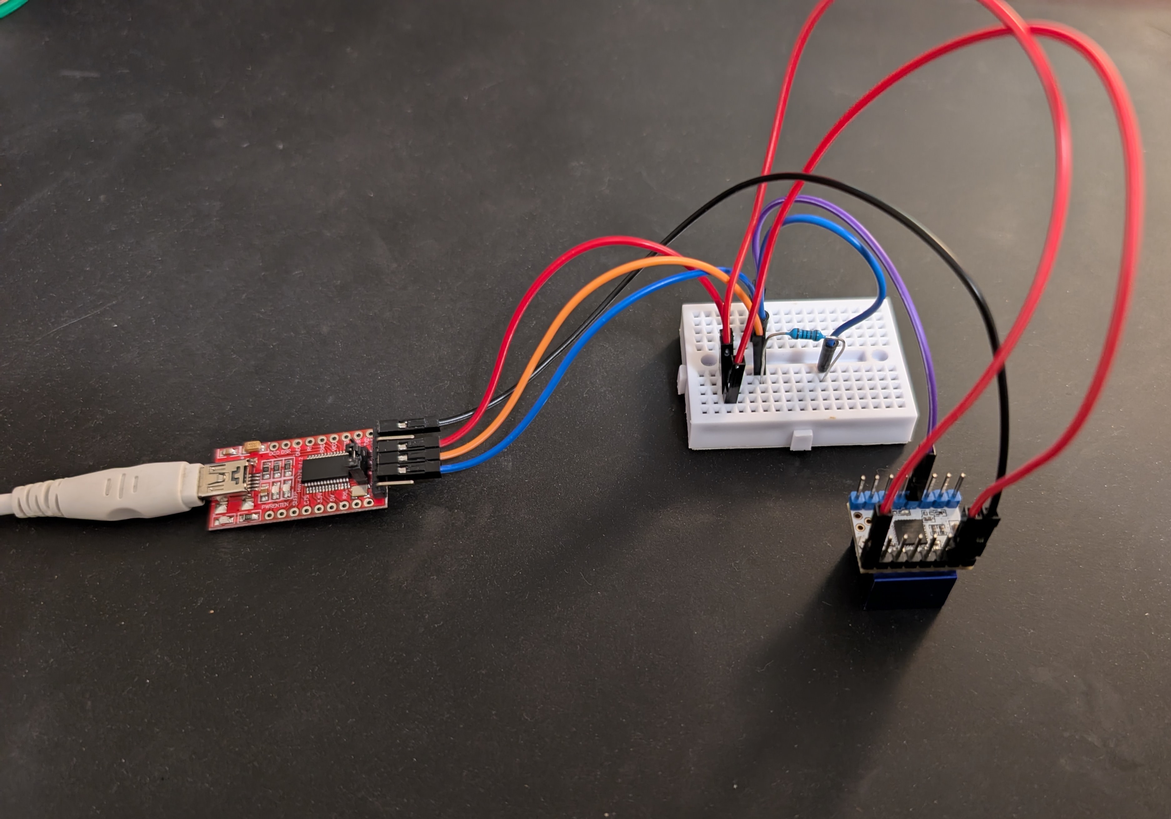
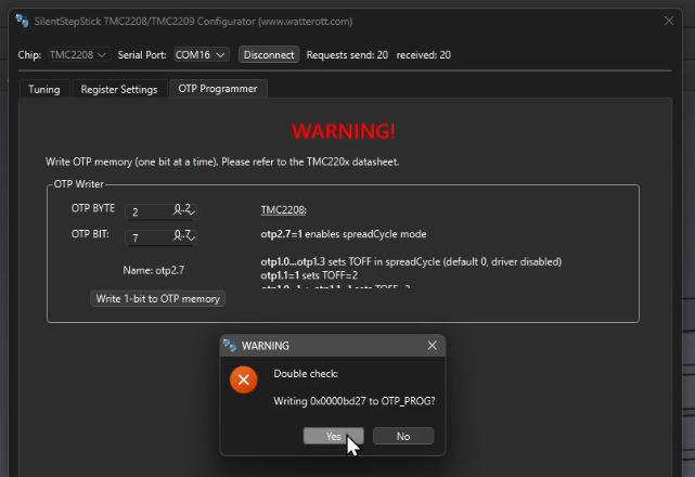
I really didn’t want to have to redesign the whole electrical enclosure, so the first thing I tried in order to cool the drivers was to put a shield between the power supply and the drivers. That did nothing, so next I tried to swap back to the TMC2208 drivers which had much larger heatsinks and to change them into “spreadcycle” mode which should let them produce more torque.
This was more complicated than I thought it would be, as it required soldering some pads on the module, connecting to it through a USB to UART adapter and permanently setting some bits in the chip with software.
After all the effort to set those up, they started stalling in around a minute of constant movement, whereas the ones I replaced lasted around 6. So I had no choice but to bite the bullet and design a new enclosure with improved cooling.
I ran another test with a very makeshift setup of a 12V PC fan blowing over the drivers and it actually worked.
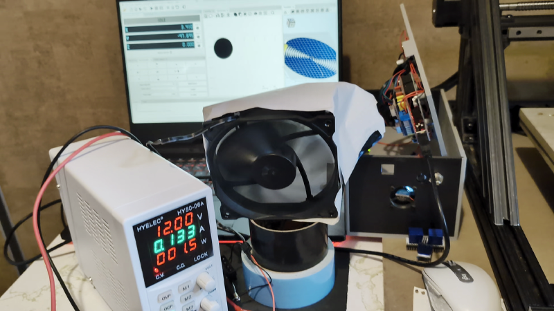
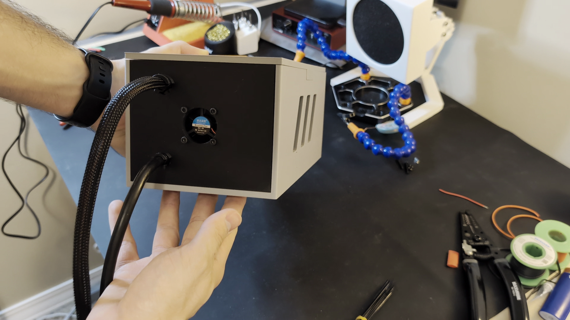
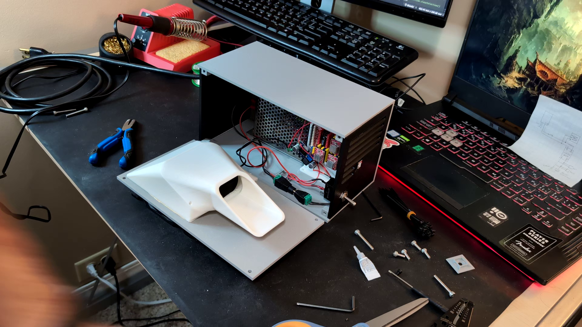
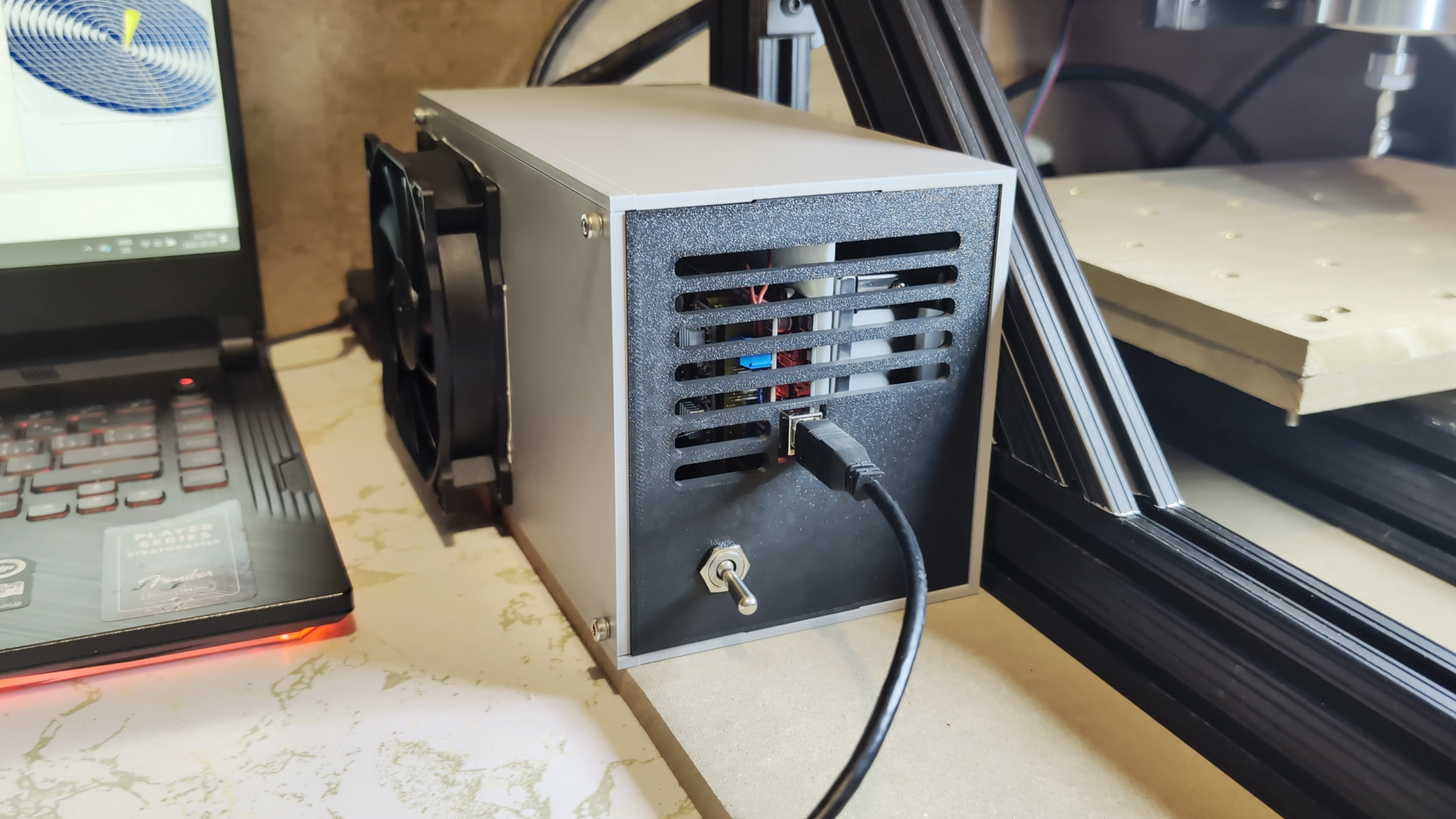
After 20 minutes of constant running the drivers barely felt warm, so I designed a new enclosure with a duct directing air from a 12V fan over the drivers.
It went together well enough and after another test it worked as expected, finally no stopping cuts every 5 minutes to let things cool down.
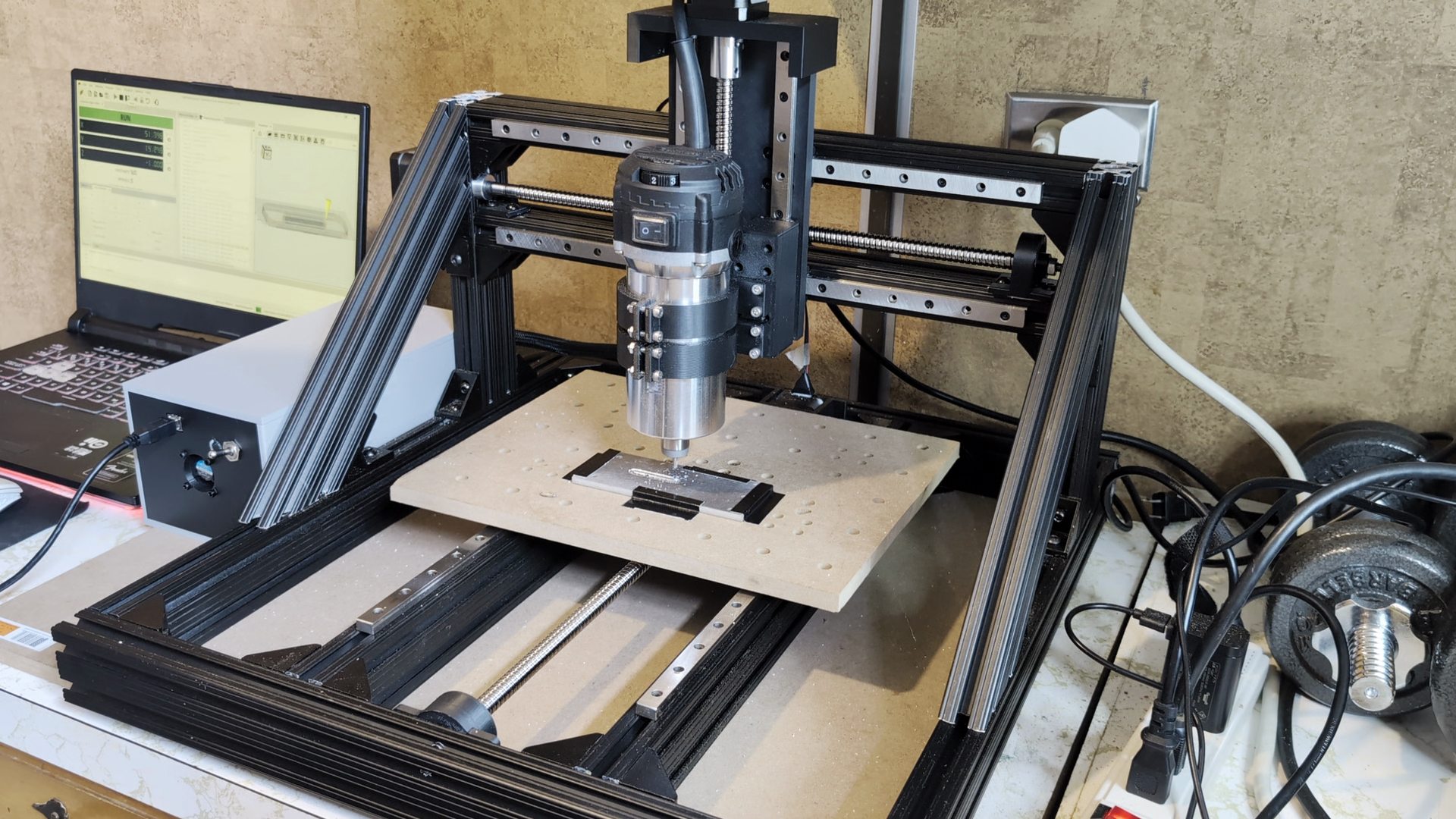
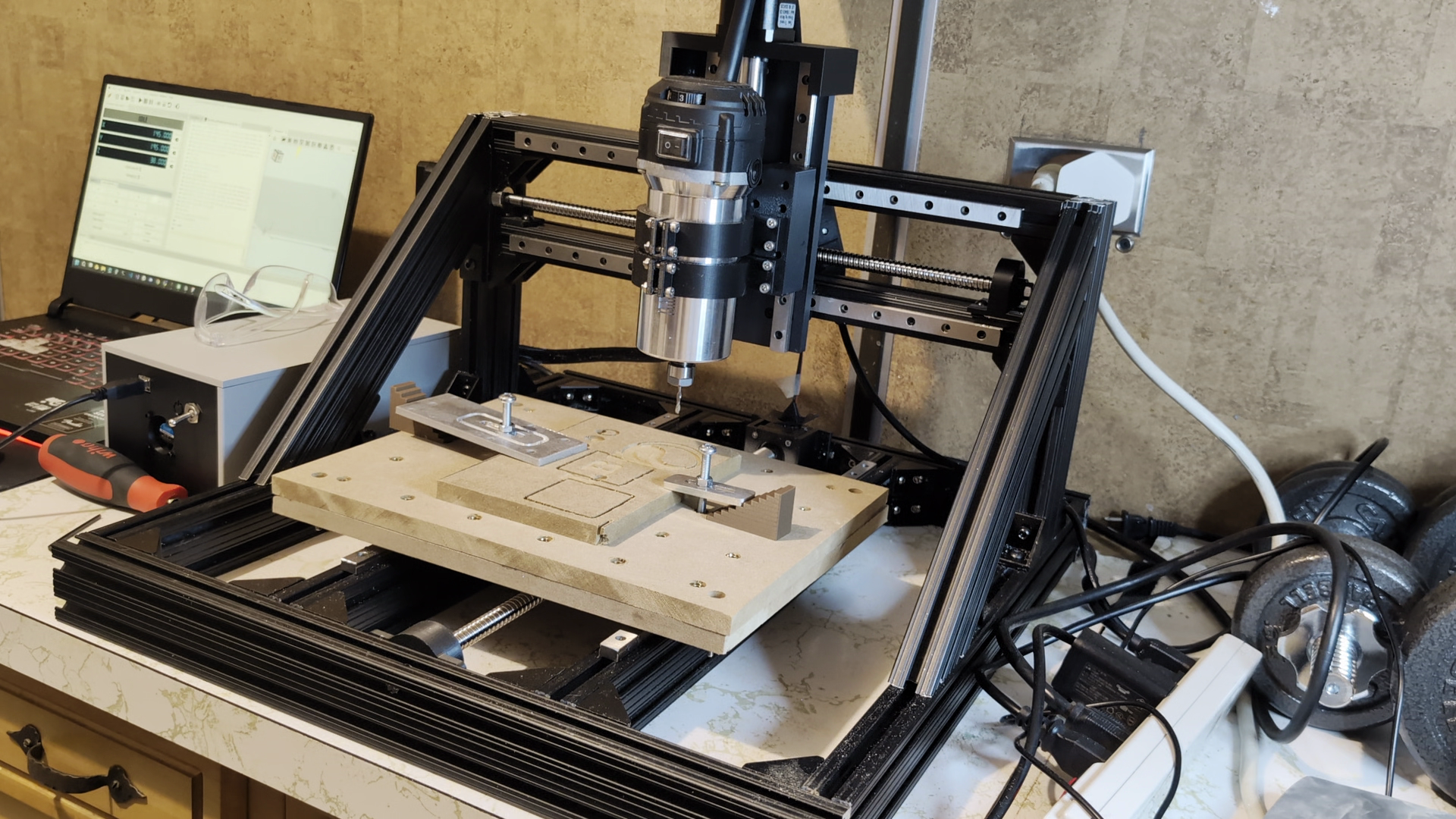
Clamp Cutting#
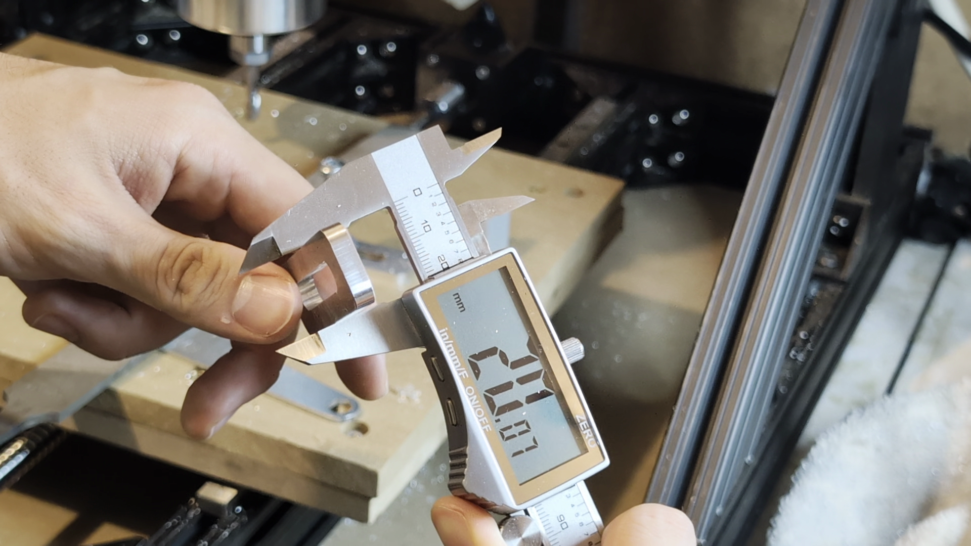
It was time for an attempt at the second workholding clamp, this time with improved rigidity, well cooled drivers, better tuned feeds and speeds, better G-code pathing, and a 1/4" endmill instead of a 1/8" one.
Using the previous workholding clamps, iso for coolant, and quite conservative settings, this cut had the best result so far. The part came out within 0.1mm of the design which impressed me!
Results and Experiments#
After this last test I was finally satisfied in calling this project finished. Though there are many more upgrades and changes that I could make, I resisted the urge I have of scope creeping projects until they never get done, which you may be able to relate to.
On the list of eventual upgrades are:
- Creating a dust shoe and vacuum system
- Setting up functional end stops for automatic homing
- Re-designing ball nut couplers for increased rigidity and using threadlocker
- Modifying the router to be controllable with G-code as a spindle
But for now, it was time to experiment with what the machine could actually do.
V-Carve#
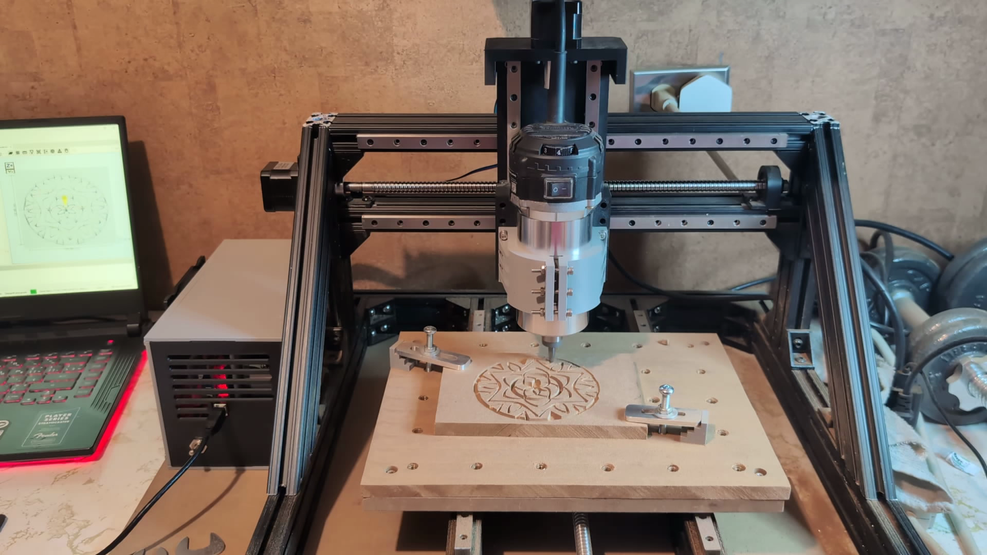
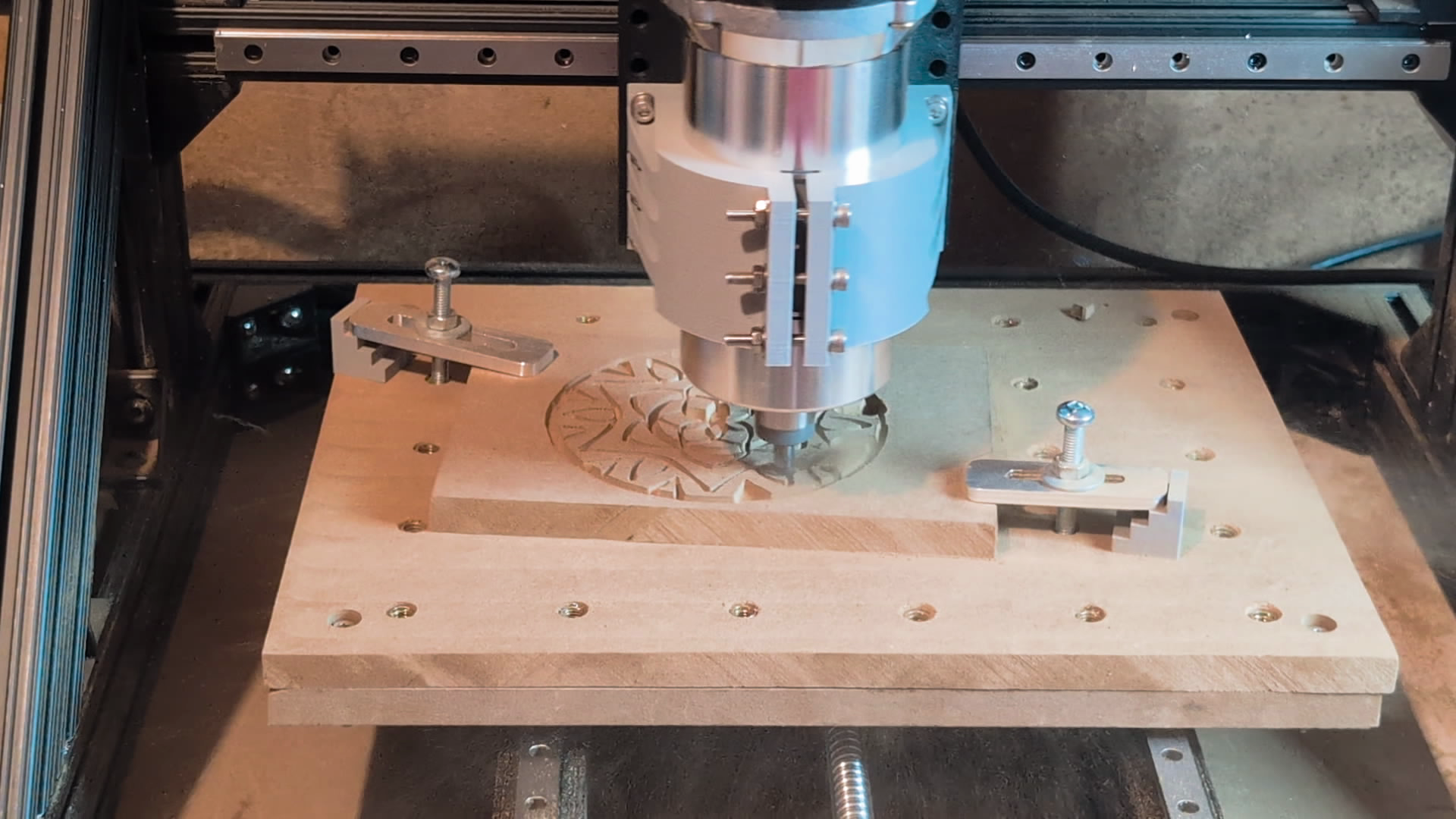
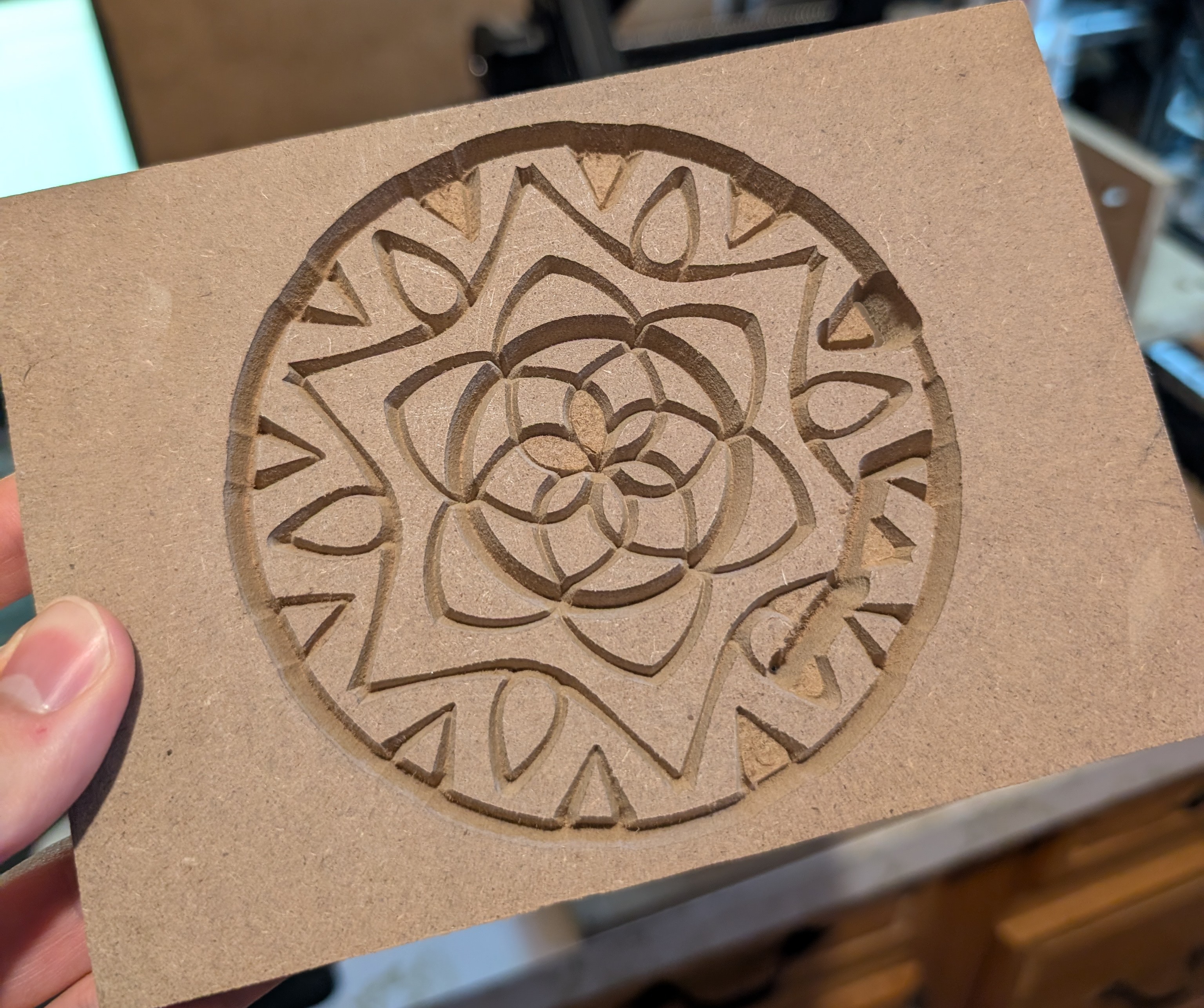
Using a V shaped bit, you can carve 2d objects using the depth of the bit to thicken the line. This is a functionality built into the FreeCAD CAM workbench, and I did a couple tests with it starting with this simple Hello.

I made a quick mandala carving which didn’t come out perfect, as I learned that MDF can rip out when cutting small delicate pieces with a large depth of cut. The Z axis nut coupler also loosened off causing the router to drop near the end and gouge the piece, a lock nut/threadlocker will prevent this in the future.
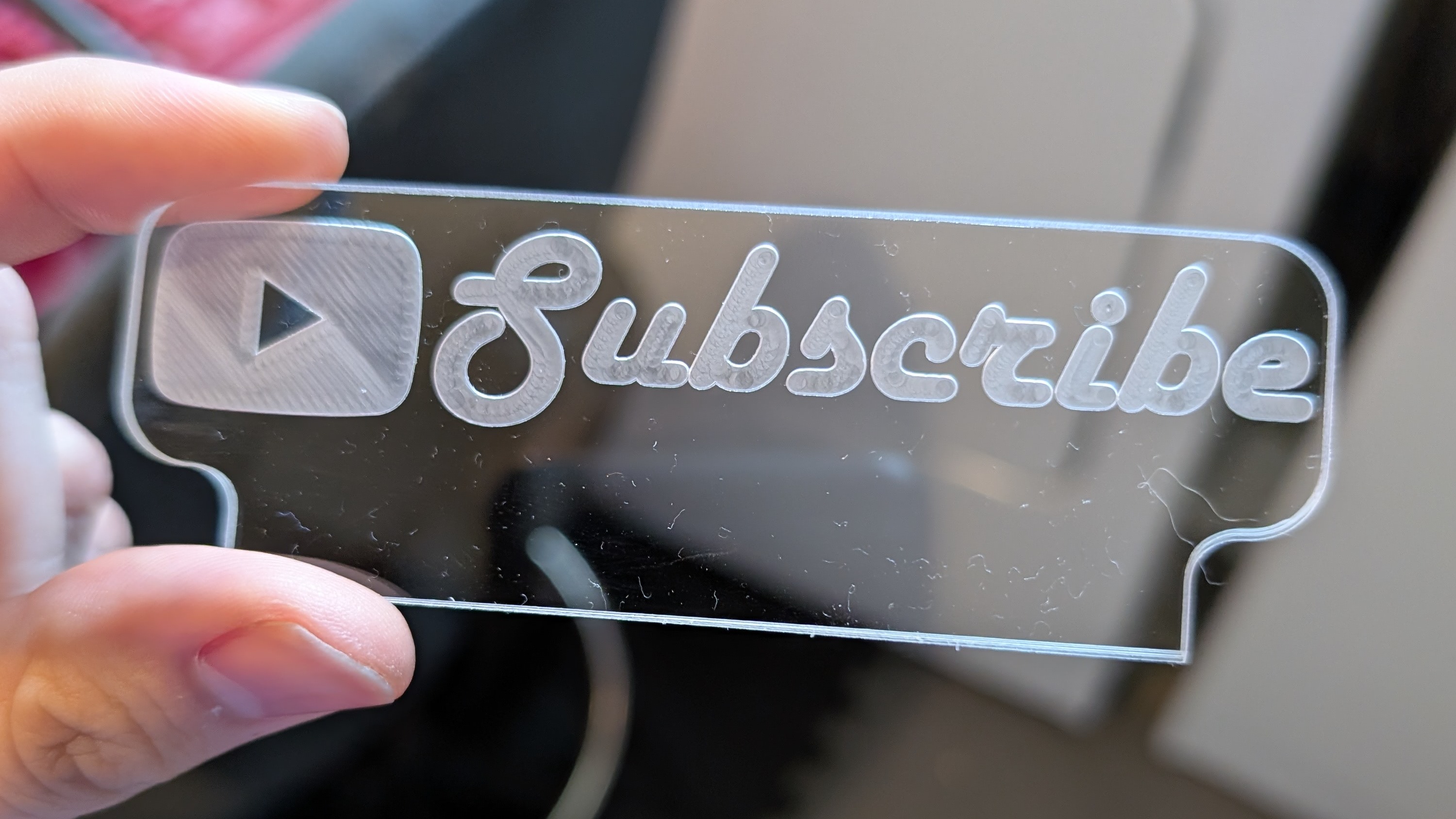
Acrylic Light Up Sign#
With a little bit of scrap acrylic, I made a very small engraved acrylic sign and a mount to light it up with LEDs.
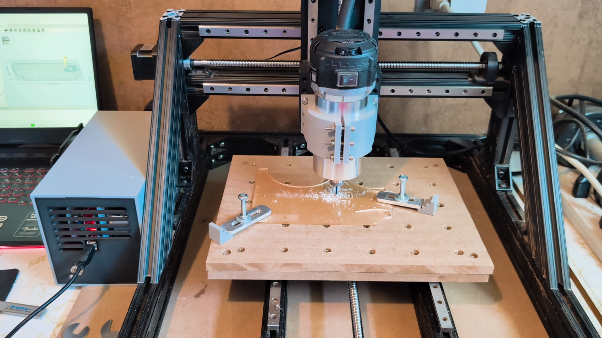

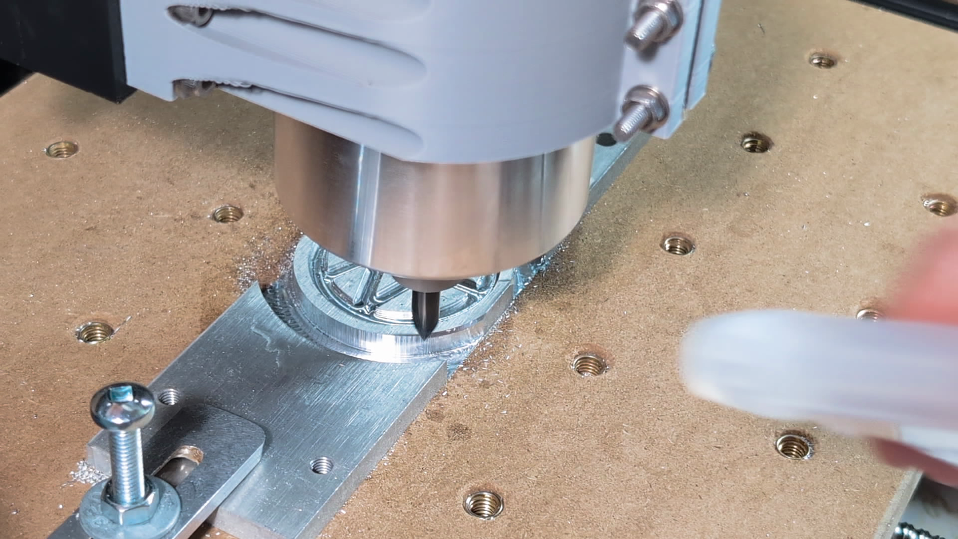
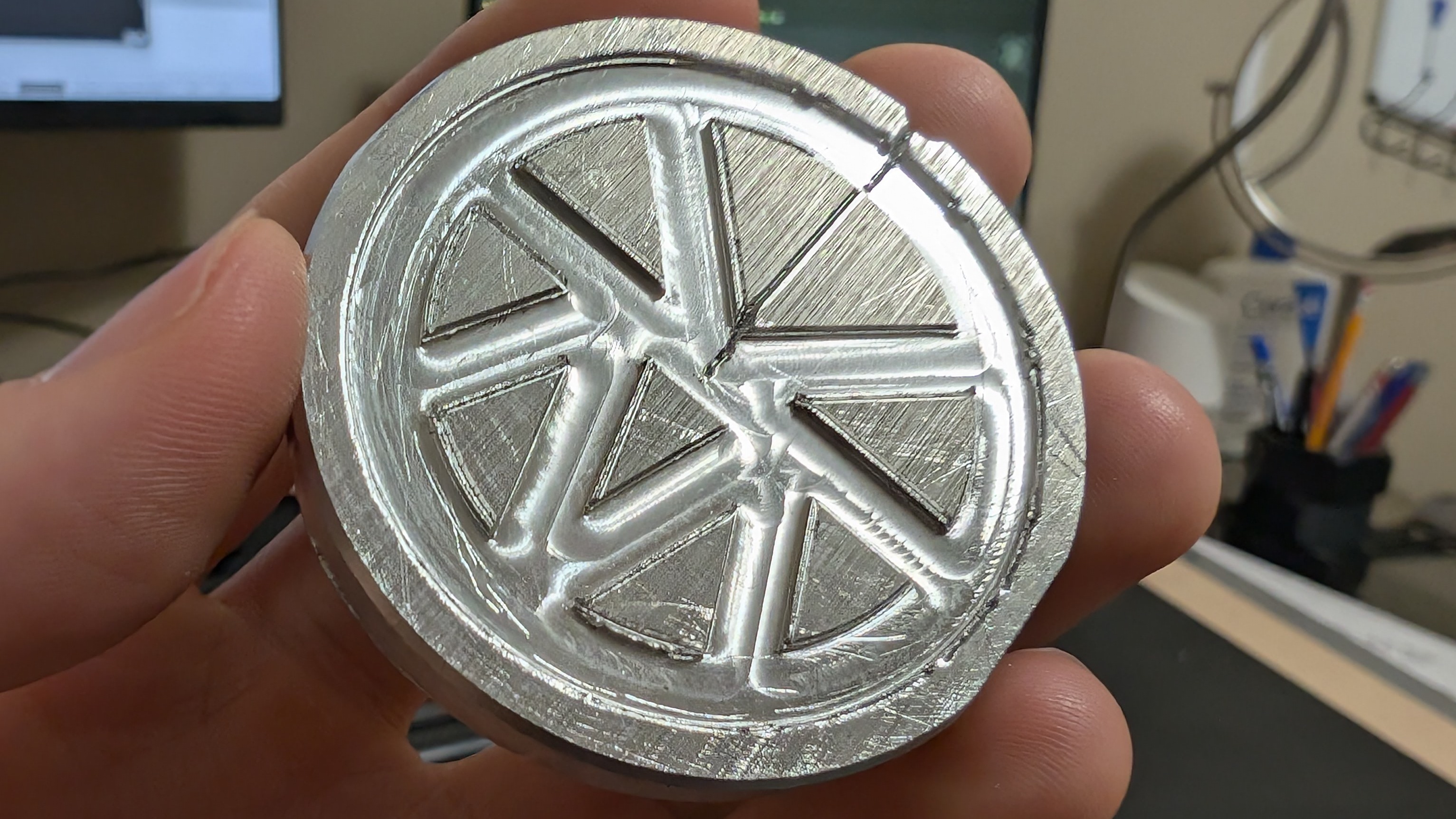
Aluminum With Chamfer#
To test the chamfer bit I created a small engraved aluminum medallion. Unfortunately I messed up the G-code for the first go at chamfering all the engraved edges causing it to crash and lose the zero point, so it didn’t come out perfect, but the chamfer around the edge of the circle still worked well.
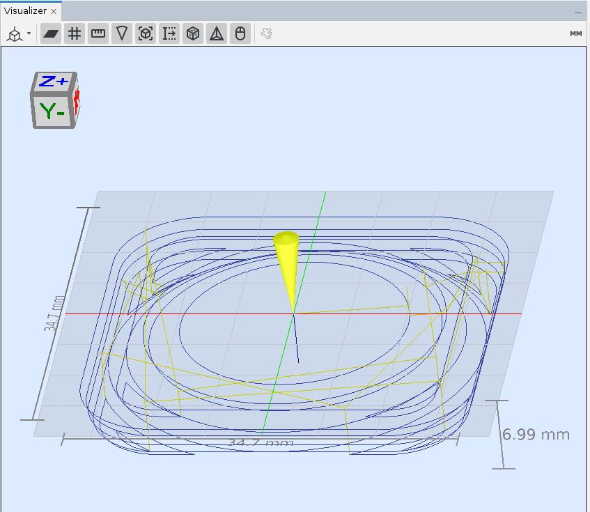
Surfacing#
The final test I did was to run a roughing and surfacing operation. FreeCAD doesn’t have great functionality for this so I used the free online tool Kiri:Moto to generate these paths instead.
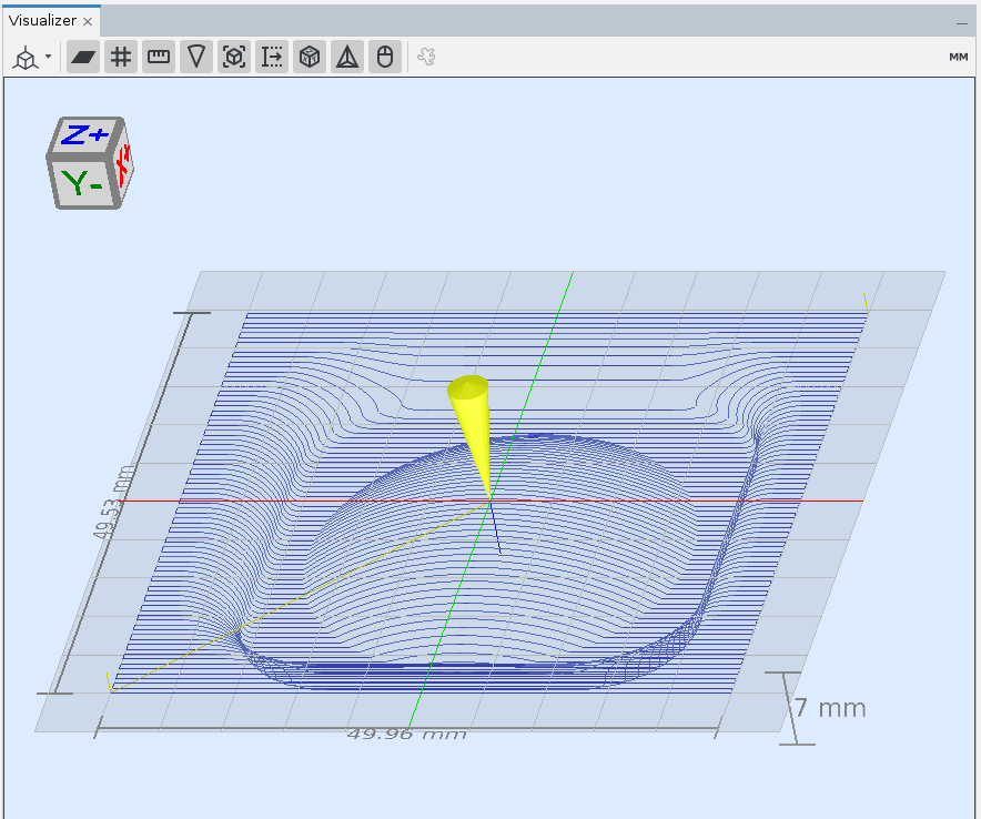
This one came out quite nice for a simple test.
Sign and Planter#
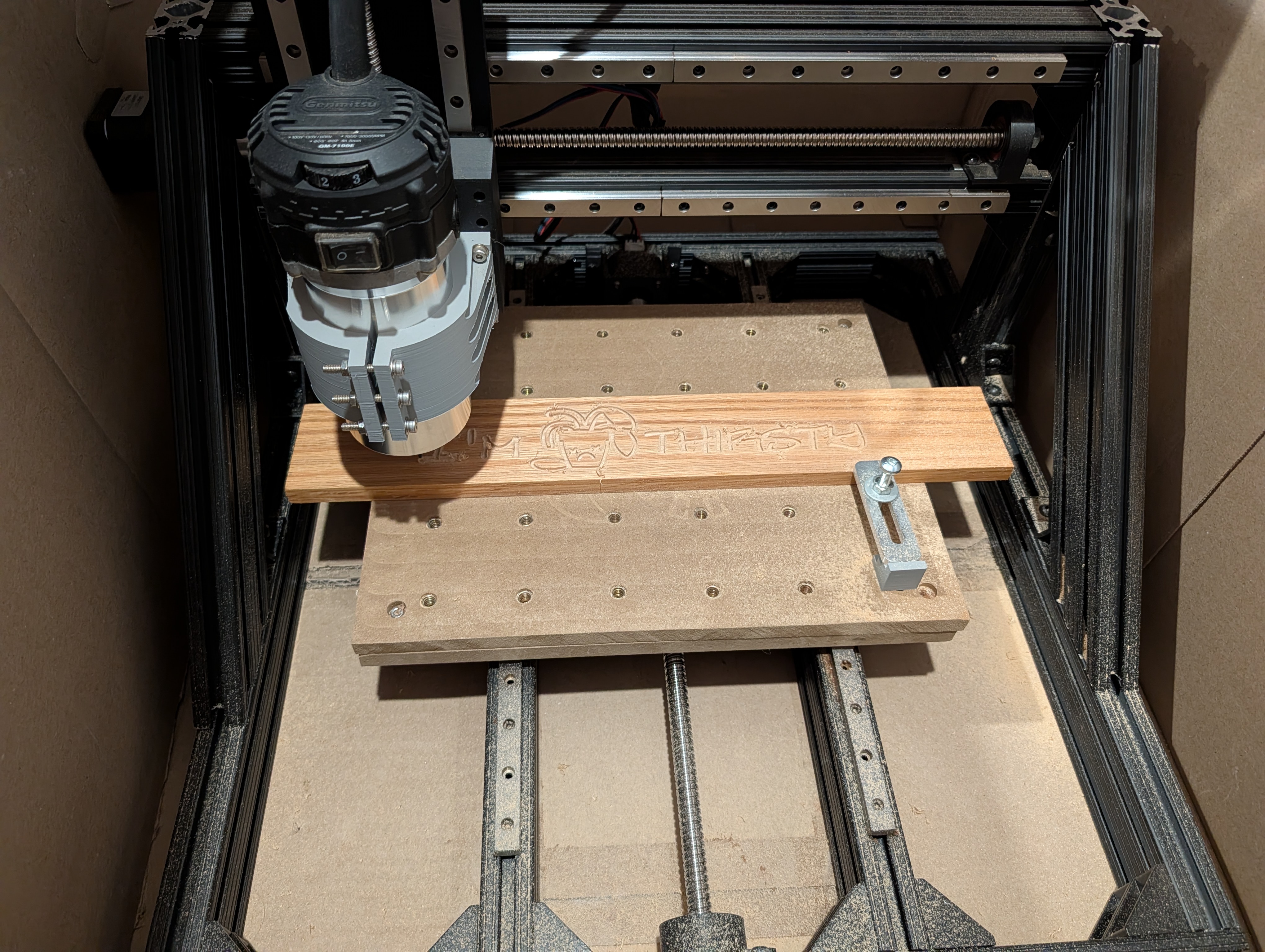
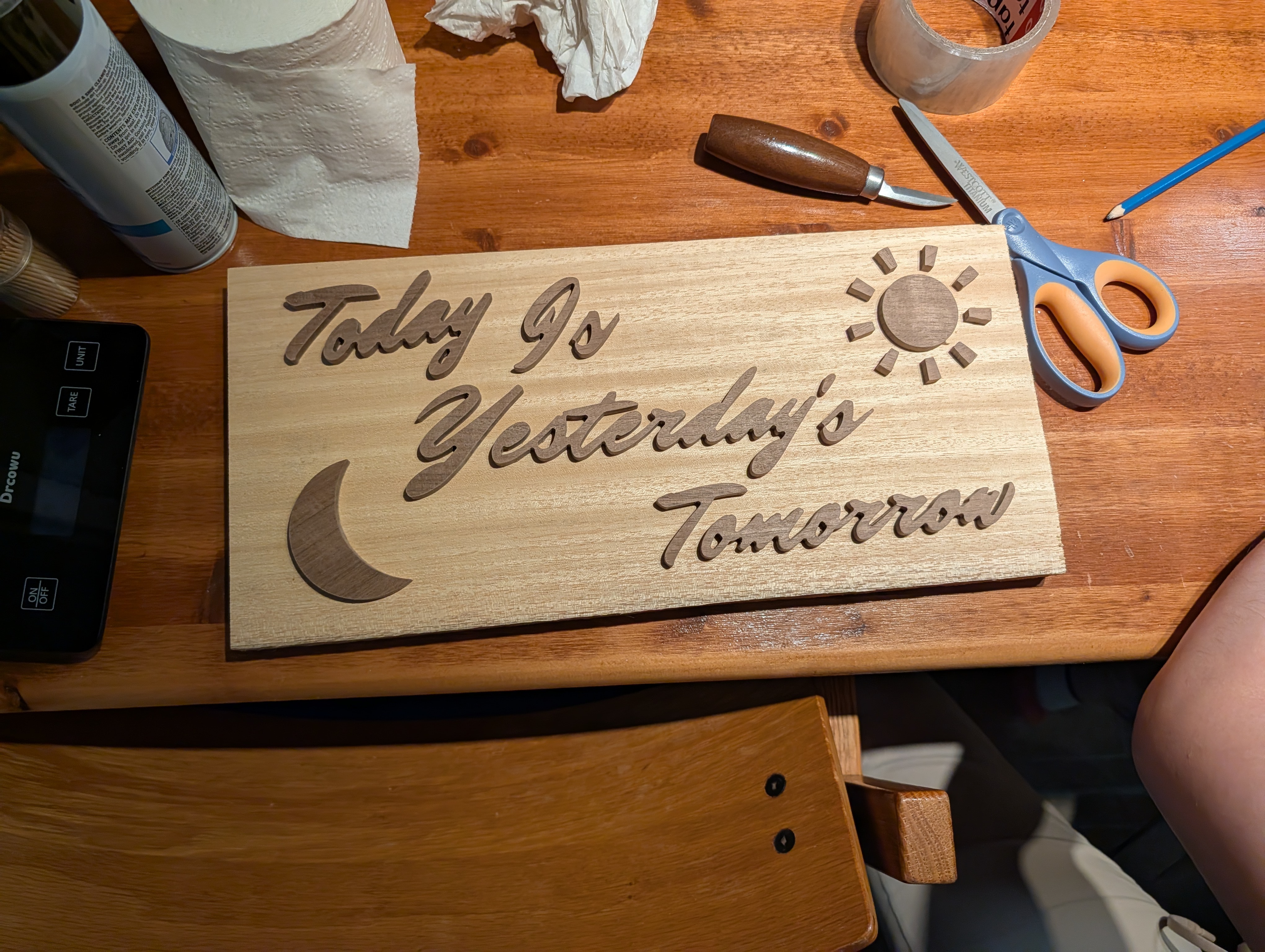
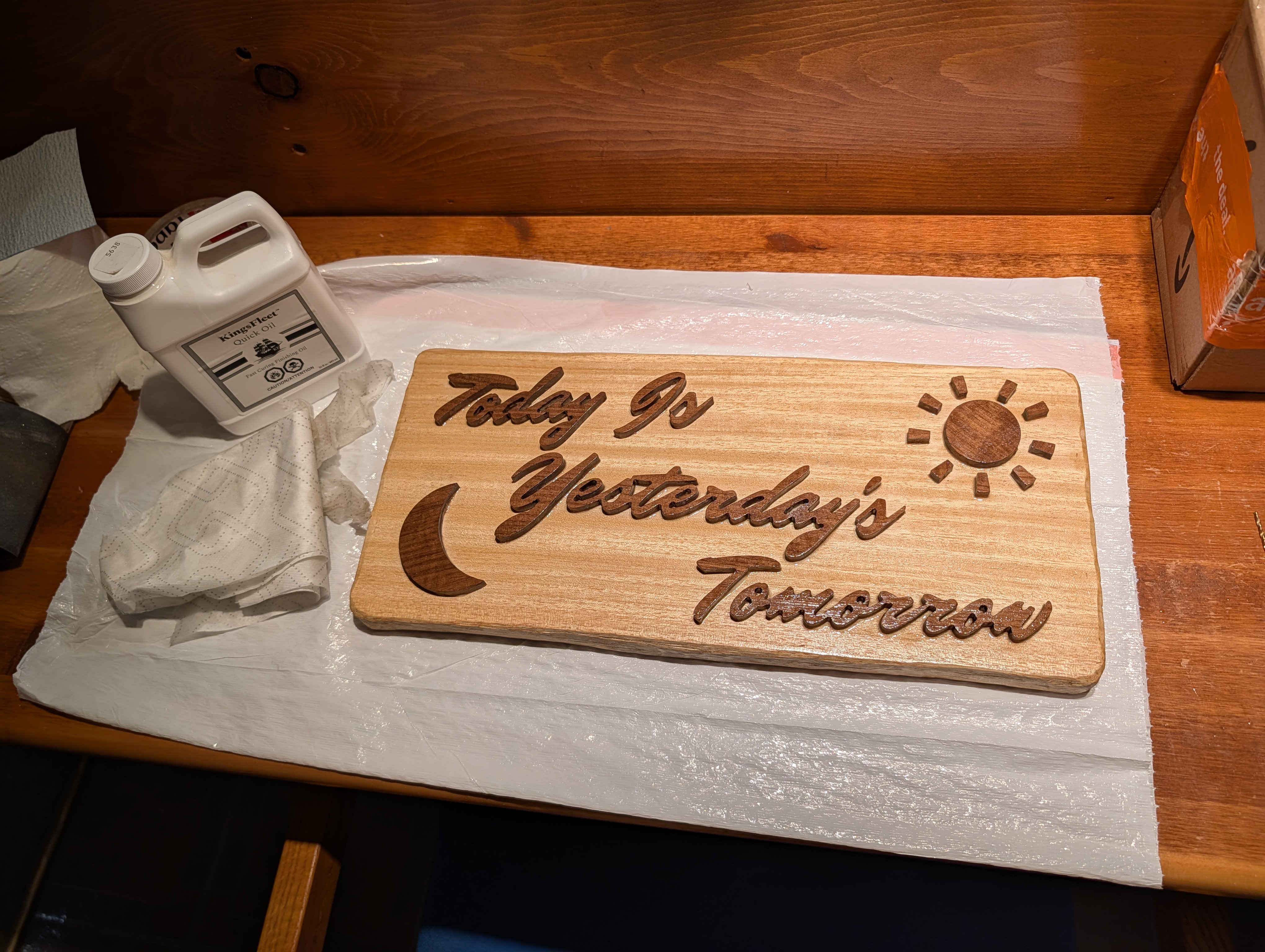
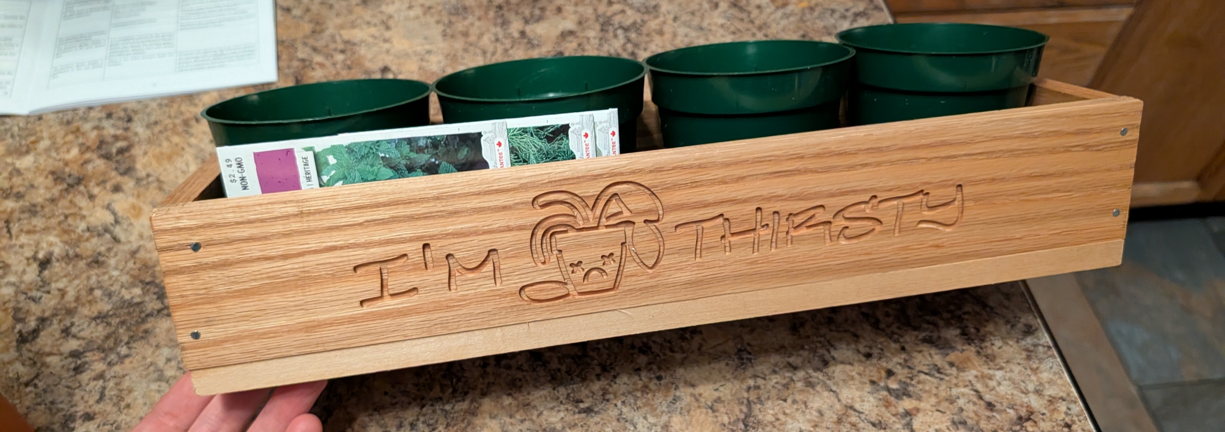
Some time after the initial build, I had a family event which I made a couple intentionally cheesy woodworking gifts for. The machine stood up well and had no problems cutting small details into black walnut and white oak with a 2mm end mill. I set it up in a cardboard enclosure to contain the sound and dust.
Final Thoughts#
Overall this project was a lot of fun, and kept me busy and learning during a period in my life where I had a lot of time on my hands. When it comes to designing machines like this I still have a lot to learn, but am very satisfied with the experience I gained making it, and with the usable finished product.
If you have any thoughts, tips, or questions feel free to reach out to me or leave a comment on the youtube video (to be released).
Resources#
Design Files#
Software Tools Used#
Configurator for TMC2208 driver